
Hello everyone, we are the Low Voltage Industry Network!
RS232, RS422, and RS485 have always been common interfaces in the low voltage industry. Many friends have mentioned the differences between them. In this issue, the Low Voltage Industry Network will summarize the main differences, which can be categorized into six aspects. Let’s take a look.
1. Differences in Interfaces and Pins
RS-232, RS-422, and RS-485 are all standards for serial data interfaces.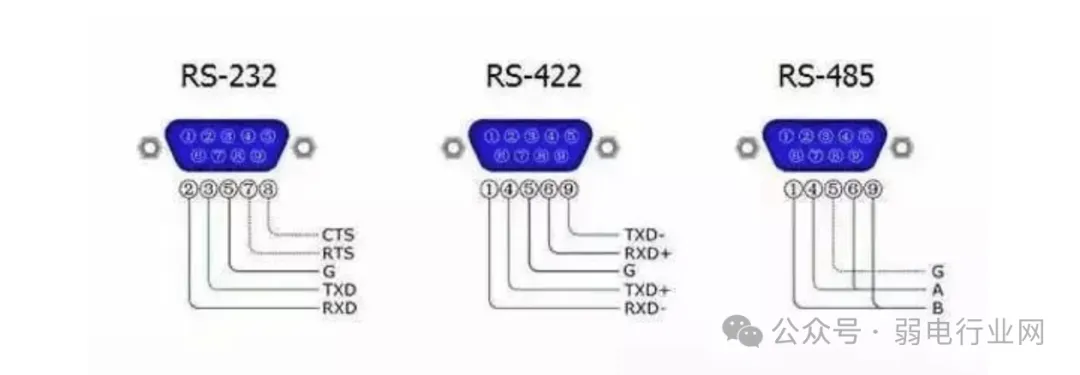 1. RS232 InterfaceRS-232 is the most widely used serial interface in PC communications. It is one of the computer communication interfaces, typically appearing in 9-pin (DB-9) or 25-pin (DB-25) configurations,with the 9-pin being more common.
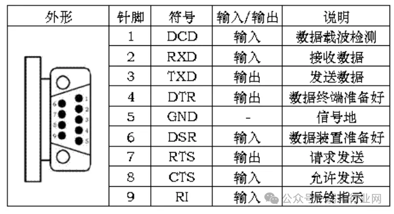 RS-232 Pins and OutputsTypically, personal computers will have two sets of RS-232 interfaces, referred to as COM1 and COM2.2. RS-422 and RS-485 InterfacesRS-422 and RS-485 differ from RS-232 in that they use differential signaling for data transmission, also known as balanced transmission, utilizing a pair of twisted wires.
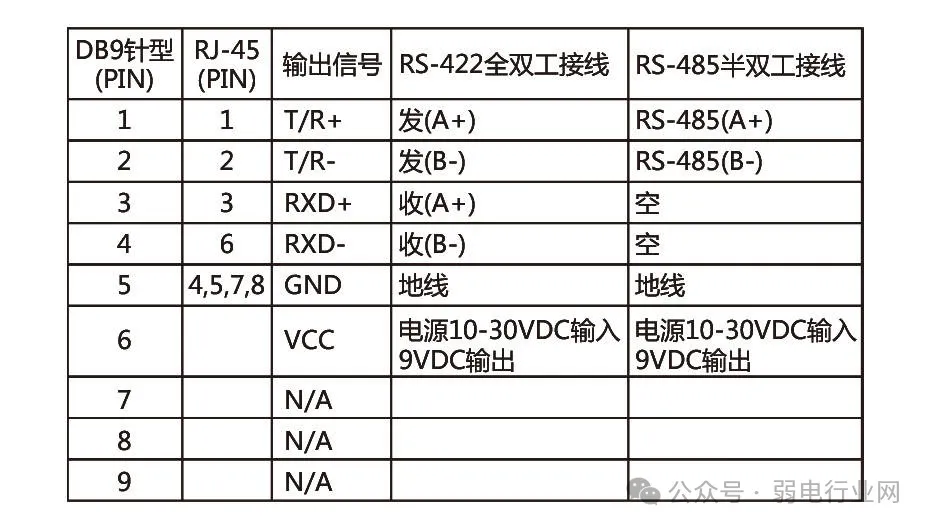
RS-485 and RS-422 Output Signals and Pins
2. Differences in Communication Distance and Speed
1. RS232:RS232 has a limited transmission distance, with a maximum standard transmission distance of 15 meters, and can only communicate point-to-point,with a maximum transmission rate of 20kB/s.2. RS422 and RS485:RS-485, like RS-422, has a maximum wireless transmission distance of 1200 meters. The maximum transmission rate is 10Mbps, but to achieve the maximum communication distance, it must operate at a transmission rate of 100Kb/s. The highest transmission rate can only be achieved over very short distances. Generally, a 100-meter long twisted pair can only achieve a maximum transmission rate of 1Mb/s.Using impedance-matched, low-loss dedicated cables can achieve distances of up to 1800 meters! Beyond 1200 meters, repeaters can be added (up to 8), which can extend the transmission distance to nearly 10Km.
3. Characteristics of the Interfaces
1. RS232: Transmits Level SignalsThe signal level values are relatively high (signal “1” is “-3V to -15V”, signal “0” is “3 to 15V”), which can easily damage the interface circuit chips. Additionally, because it is not compatible with TTL levels (0~”<0.8V”, 1~”>2.0V”), a level conversion circuit is required to connect with TTL circuits. Furthermore, it has poor anti-interference capability.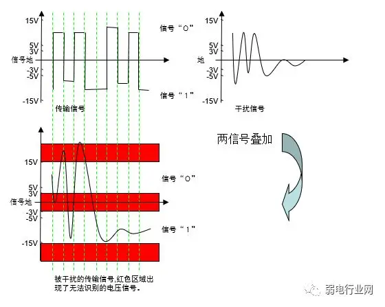 2. RS485: Transmits Differential SignalsLogic “1” is represented by a voltage difference of + (2—6) V between the two wires; logic “0” is represented by a voltage difference of – (2—6) V. The signal level of the interface is lower than that of RS-232, making it less likely to damage the interface circuit chips, and this level is compatible with TTL levels, allowing for easy connection with TTL circuits, with strong anti-interference capability.
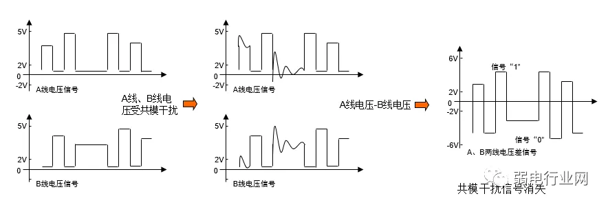 3. RS422: Transmits Differential SignalsSince RS-485 is developed from RS-422, the electrical performance of RS-422 is identical to that of RS-485. The main difference is:
RS-422 has 4 signal lines:two for transmission (Y, Z) and two for reception (A, B). Since RS-422 separates receiving and transmitting, it can send and receive simultaneously (full duplex).
RS-485 has 2 signal lines:both sending and receiving are done through A and B. Since RS-485 shares the two lines for receiving and transmitting, it cannot send and receive simultaneously (half duplex).


START

4. Working Modes and Communication Methods
1. Working Modes:RS232:3-wire full duplexRS485:2-wire half duplexRS422:4-wire full duplex2. Communication Methods:RS232:Point-to-point communicationRS422 and RS485:Point-to-multipoint master-slave communicationAs shown in the figure below: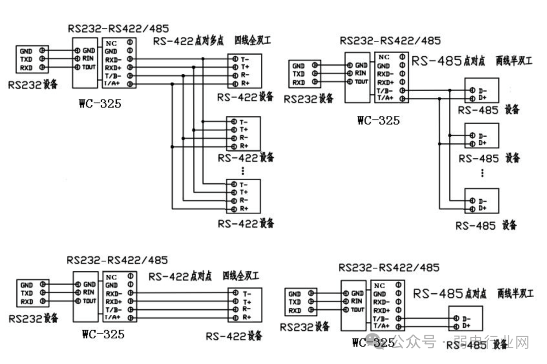
5. Interface Conversion
1. RS232 to RS485 Conversion 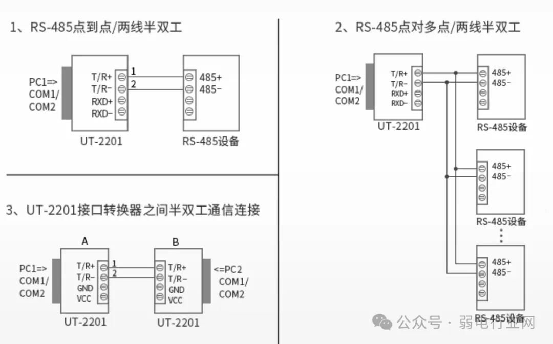 2. RS232 to RS422 Conversion
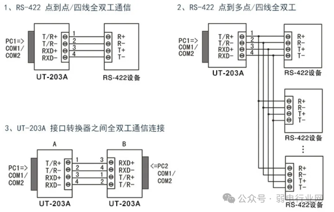 It can be seen that RS232 typically has a 9-pin configuration, RS422 generally only uses four wires for communication, and RS485 usually communicates using two shielded twisted wires, making a 9-pin interface unnecessary.
Finally, the Low Voltage Expert adds:
What to do if data communication fails? Here are several aspects to troubleshoot.
1. Check if the RS-232 interface wiring is correct
2. Check if the RS-485/RS-422 output interface wiring is correct
3. Check if the power supply is normal
4. Check if the terminal connections are good
5. Observe if the send/receive indicator lights flash during reception


START

 Recommended Learning:VIP Technical Exchange Group: Click hereLow Voltage Solutions and Quotes: Click hereComplete Low Voltage Drawings: Click here