1. Usage of Multimeters
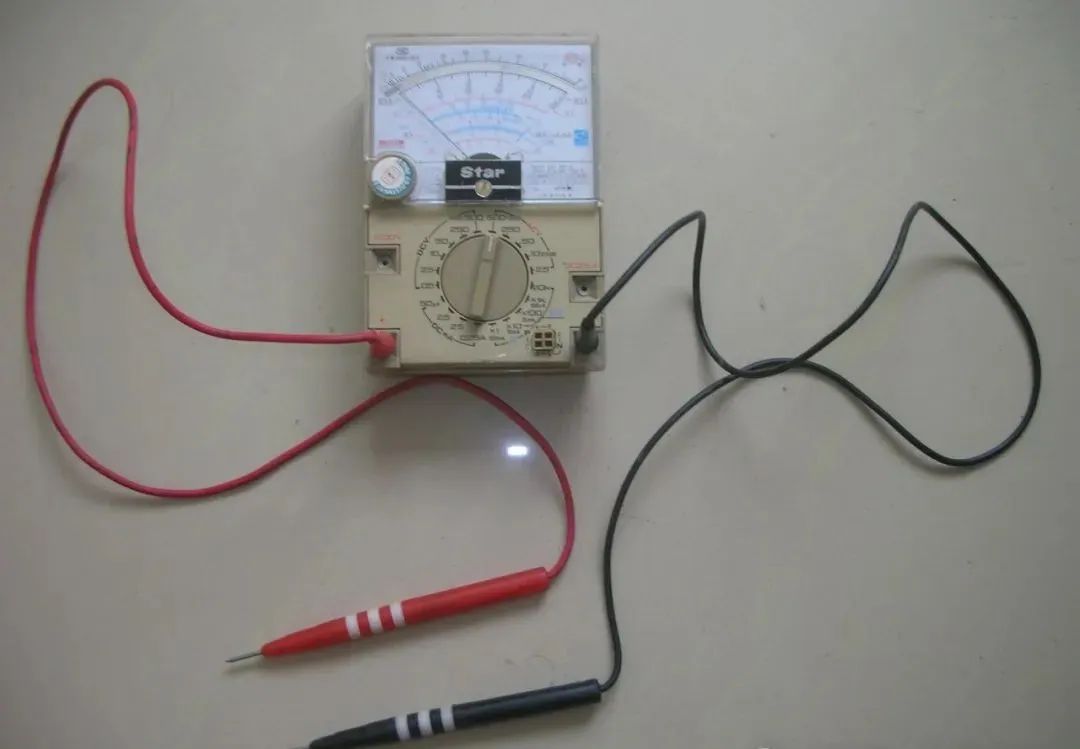
1. Understanding Common Symbols on Multimeters
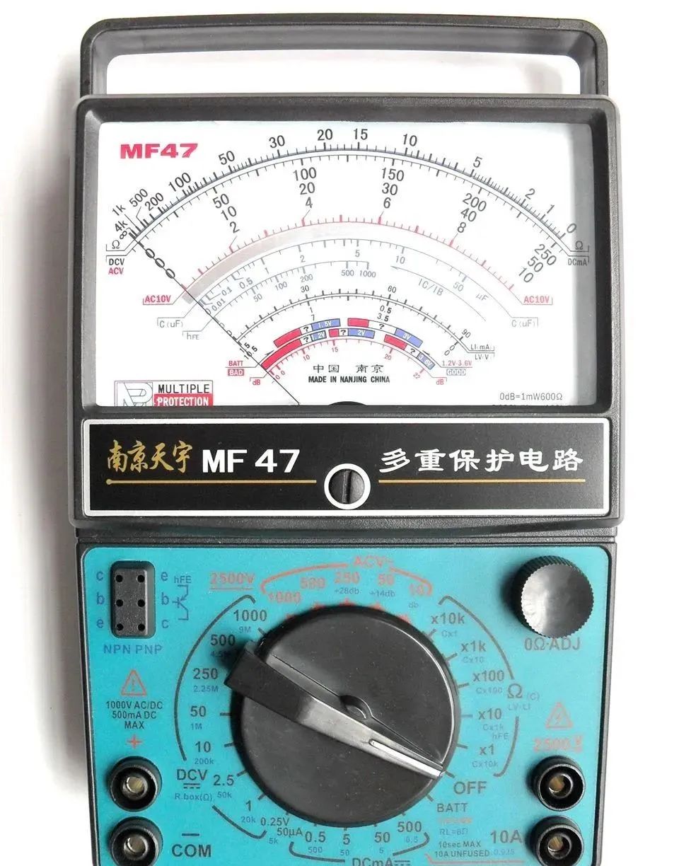
Types of electrical measurements and switch positions:
ACV (or V) — AC voltage range, typically includes 2.5V, 10V, 50V, 250V, 500V, etc.
DCV (or V) — DC voltage range, typically includes 0.5V, 2.5V, 10V, 50V, 250V, 500V, etc.
DCmA (or mA) — DC milliamp range, typically includes 50μA, 2.5mA, 25mA, 0.25A, etc.
Ω — Resistance range, typically includes ×1, ×10, ×100, ×1K, ×10K, etc.
(Others omitted)
2. Measuring DC Current with a Multimeter (mA)
(1) Set the multimeter switch to the appropriate DCmA or mA range and mechanically zero it.
(2) Select the correct polarity for the probes and connect them in series with the circuit.
(3) If the size of the DC current is unknown, start from the highest range and adjust downwards.
(4) During measurement, ensure the pointer falls within the range of the scale.
(5) Read the measurement correctly.
Notes: 1. Only small DC currents can be measured.
2. A resistor (load) must be connected in series.
3. Pay attention to probe polarity. Red is positive, black is negative.
3. Measuring DC Voltage with a Multimeter
(1) Set the switch to the appropriate DCV (or V) range and mechanically zero it.
(2) If the voltage size is unknown, start from the highest range and adjust downwards.
(3) Connect the probes with the correct polarity to the circuit.
(4) During measurement, ensure the pointer falls within the range of the scale.
(5) Read the measurement correctly (read the multiplier of 10).
Notes: 1. If the size of the DC voltage to be measured is unknown, set to the maximum DC voltage range.
2. Pay attention to probe polarity. Red is positive, black is negative.
3. Ensure safety.
4. Measuring AC Voltage with a Multimeter
(1) Set the switch to the appropriate ACV (or V) range and mechanically zero it.
(2) If the voltage size is unknown, start from the highest range and adjust downwards.
(3) Connect the probes to the power supply (use 250V range for single-phase, 500V range for three-phase).
(4) Read the measurement correctly (read the multiplier of 10).
**Notes: 1. If the size of the AC voltage to be measured is unknown, set to the maximum AC voltage range. AC voltage has no positive or negative polarity, and there are no directional requirements for the probes.
2. When measuring AC voltage, ensure the multimeter’s pointer is as close to the range as possible.
3. Ensure safety.
4. When not in use, set the multimeter to the maximum AC voltage range.
5. Measuring Resistance with a Multimeter:
(1) First estimate the approximate resistance value to be measured, set the switch to the appropriate Ω range, if unknown, start from the X100 range and mechanically zero it. Follow the public account: Jibao Xiaojia, a platform for learning technology.
(2) Short the two probes to zero the ohm measurement.
(3) Connect the two probes to the terminals of the resistance to be measured, and read the scale on the meter.
(4) Multiply the reading by the selected range multiplier to obtain the actual resistance value (in ohms).
(5) Notes:
a. When measuring resistance, ensure the multimeter’s pointer is as close to the 1/2 to 2/3 position on the scale as possible.
b. Always mechanically zero the meter before changing ranges, and re-zero when switching to another range.
c. Do not touch both ends of the resistance with your hands while measuring.
d. Measurements should be taken when the circuit is de-energized.
e. At least one end of the resistance being measured should not be connected to other components.
f. If the multimeter cannot adjust to ‘0’ in the Ω range ×1, it may be due to insufficient battery power and should be replaced.
6. Checking Capacitors with a Multimeter
(1) Set the switch to the Ω range at ×1K and zero it.
(2) Connect the two probes to the capacitor, observing that at the moment of connection, if the meter pointer swings towards ‘0’ Ω and quickly returns to ‘∞’, the capacitor is good; if not, the capacitor is faulty.
(3) Notes:
a. If the first connection is unclear, switch the probes and retest.
b. At least one end of the capacitor should not be connected to other components.
c. If the capacitance is too small, this method may not show the pointer movement, and an amplification stage may be needed for accurate measurement (or use a capacitance meter).
7. Checking Diodes with a Multimeter
(1) Set the switch to the Ω range at ×1K and zero it.
(2) If the negative probe is connected to the upper side of the diode and the positive probe to the lower side, the meter should show a high resistance (reverse resistance), generally above several hundred kΩ; then switch the probes and measure again, if the resistance is low (forward resistance), generally below several kΩ, the diode is good, indicating the lower side is positive and the upper side is negative.
(3) If both the forward and reverse resistances are high or low, the diode is faulty.
8. Checking Motors and Transformers for Open or Short Circuits with a Multimeter
(1) Disconnect the motor winding connections, set the multimeter to the Ω range at ×10 or higher, and measure across the terminals of each winding; if the pointer moves, the winding is intact.
(2) Use the multimeter at ×1K to measure the resistance between the winding wires; if the pointer does not move, there is no short circuit (similarly, check for shorts between the coil and the casing).
**Notes: 1. When measuring resistance, ensure the multimeter’s pointer is as close to the 1/2 to 2/3 position on the scale as possible.
2. When not in use, set the multimeter to the maximum AC voltage range.
3. If the multimeter cannot adjust to ‘0’ in the Ω range ×1, it may be due to insufficient battery power and should be replaced.
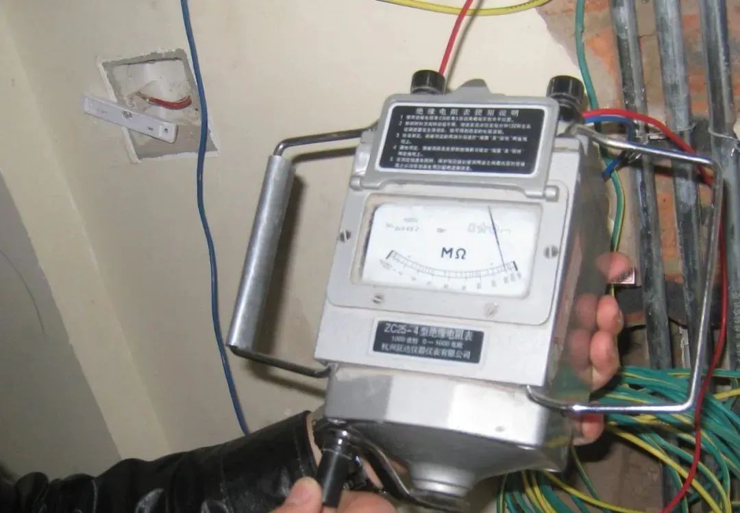
2. Usage of Insulation Resistance Meters (Megohmmeters)
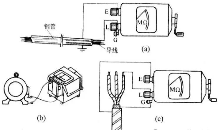
Wiring for measuring cable insulation resistance
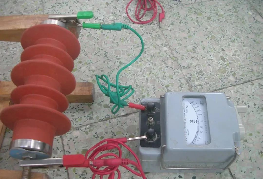
Insulation Resistance:
Refers to the ratio of the DC voltage applied to the test specimen to the leakage current flowing through the specimen. Measuring insulation resistance is one of the simplest and most commonly used methods to understand electrical equipment. Since the current flowing through the insulating medium can be surface current and volume current, insulation resistance can also be divided into volume insulation resistance and surface insulation resistance. What we are really concerned about is the volume insulation resistance.
Absorption Ratio: The ratio of the insulation resistance at 60 seconds to that at 15 seconds is commonly referred to as the absorption ratio K, which is significantly related to the insulation condition.
Polarization Index: The ratio of the insulation resistance measured at 10 minutes to that at 1 minute.
1. Selection of Megohmmeters:
Choose a 2500V meter for equipment rated above 1000V; for equipment rated at 35kV and above, select a 5000V or 10000V insulation resistance meter.
2. Checking the Functionality of the Megohmmeter: In an open circuit state at the measurement end, quickly (at a uniform speed of 120 turns per minute) rotate the handle of the megohmmeter with the line terminal “L” and the ground terminal “E” suspended; the pointer should point towards the “∞” position. Then short the two measurement ends, slowly rotate the handle, and the pointer should point to the “0” Ω position; if so, the megohmmeter is good for use; otherwise, it cannot be used.
3. Must be in a powered-off state and discharge the equipment to be measured.
4. Correct Wiring: Clean the surface of the test specimen and wire correctly. Connect the line terminal “L” of the insulation resistance meter to the conductor; connect the ground terminal “E” to the ground wire and connect it to the grounding device. Ensure that the single wire connected to the “L” terminal is insulated from the ground and must be suspended in the air.
5. Reading the Megohmmeter: Start slowly, and if the pointer is not at “0”, then rotate the handle at a uniform speed of 120 turns per minute. After shaking for 1 minute at the specified speed of 120 r/min, read the stable pointer position.
6. Stopping Discharge: Without stopping the shaking, wear gloves to disconnect the “E” connection wire. After the shaking handle stops, discharge the removed “E” by touching it to the “L” terminal.
7. Determining Insulation Parameter Compliance: Low Voltage: The test procedure specifies that 1V/1000Ω insulation is good. Insulation resistance for electrical equipment below 500 volts should be greater than or equal to 0.5MΩ to be considered good insulation. For special low-voltage devices such as motors, insulation resistance should be greater than or equal to 1MΩ to be considered good insulation. High Voltage: Insulation resistance for high voltage electrical equipment at 10kV should be greater than or equal to 1000MΩ; for 35kV, it should be greater than or equal to 1500MΩ; for 110kV, it should be greater than or equal to 2000MΩ;
Standards for Insulation Resistance of Insulators: (1) The insulation resistance of each new insulator should be greater than or equal to 500MΩ. (2) The insulation resistance of each insulator in operation should be greater than or equal to 300MΩ.
3. Usage of Clamp Meters
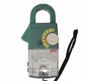
1. Purpose of Clamp Meters:
Clamp meters are used to measure AC current in circuits.
The advantage is that they can measure AC current without interrupting the circuit; the disadvantage is that the measurement error is large.
2. Precautions for Using Clamp Meters
(1) MG26 can only be used for measuring AC circuits below 500V; GL-9000 high voltage clamp meter is for measuring voltages below 35kV.
(2) Only one wire can be clamped at a time.
(3) The core clamp must be securely closed.
(4) To determine the size of the AC current, select the appropriate range; if the current is unknown, set it to the maximum range.
(5) The instrument should be placed horizontally during measurement.
(6) Do not change ranges or repair the instrument during measurement; if a range change is needed, remove the measured circuit, set the range, and then measure.
(7) If measuring a current less than 1A, wrap the wire around the clamp several times; the actual reading is the dial reading divided by the number of turns.
(8) If using a multimeter for voltage measurement, set it to the appropriate voltage range, then use the two probes to measure the voltage.
Ground Resistance Meter Usage
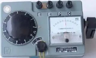
1) Measuring Instruments and Principles
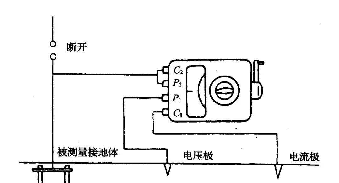
Ground resistance values are generally determined using ground resistance measuring instruments. Ground resistance measuring instruments are specialized devices for measuring ground resistance. Common ground resistance measuring instruments are equipped with a hand-cranked generator, and the main accessories include three measuring wires and two measuring electrodes. Ground resistance measuring instruments typically have four terminals: C2, P2, P1, C1 or three terminals (E, P, C). During measurement, the current electrode and voltage electrode are driven into the ground at a certain distance from the grounding body to be measured; connect the C2 and P2 terminals or connect the E terminal (black 5-meter insulated wire) to the grounding body to be measured, connect the P1 terminal or P terminal (green 20-meter insulated wire) to the voltage electrode, and connect the C1 terminal or C terminal (red 40-meter insulated wire) to the current electrode; select the appropriate multiplier (from X10 to X1 to X0.1, adjusting until reasonable), and continuously crank the handle at a speed of about 120 turns per minute while adjusting the potentiometer knob until the meter pointer stabilizes at the center position, then read the value from the scale; multiply the reading by the multiplier to obtain the measured ground resistance value.
2) Measurement Methods and Precautions
When using a ground resistance measuring instrument to measure ground resistance, the following issues should be noted:
① Check that the ground resistance measuring instrument and its accessories are intact, perform a mechanical zeroing, and conduct a short-circuit calibration and open-circuit judgment to check for instrument errors.
② For grounding devices that are electrically connected to the power distribution network, it is best to disconnect from the power distribution network before measurement to ensure measurement accuracy and prevent feedback of the measuring power source to the power distribution network, which could cause other hazards.
③ Correct wiring. Refer to the external wiring diagram in Figure 2.20.
④ After wiring, place the instrument horizontally and select an appropriate multiplier to improve measurement accuracy. Then, measurement can begin.
⑤ Measurement connections should avoid running parallel to nearby overhead lines to prevent induced voltage hazards.
⑥ Select an appropriate measurement distance to improve measurement accuracy. For linear arrangements of measuring electrodes, for a single vertical grounding body or a composite grounding body with a small footprint, the distance between the current electrode and the grounding body to be measured can be 40m, and the distance between the voltage electrode and the grounding body can be 20m; the current electrode and voltage electrode should be arranged at a 90-degree angle or in a straight line.
⑦ The arrangement of measuring electrodes should avoid running parallel to underground metal pipes to ensure the authenticity of the measurement results.
⑧ Measurements should generally not be taken in rainy weather; measurements should be conducted after a continuous period of 7 days without rain; measurements of grounding resistance for lightning protection devices should not be taken during thunderstorms.
⑨ If the measured ground resistance is very small and the measurement connection wire is long, separate C1 and P2, and connect them to the grounding body to reduce measurement errors.
3) Ground Resistance Compliance
For lines and equipment below 500V or 10kV with transformer capacities less than 1000kVA, the grounding resistance should be less than or equal to 10Ω.
For lines and equipment below 500V or 10kV with transformer capacities greater than 1000kVA, the grounding resistance should be less than or equal to 4Ω.
For equipment at 110kV and above, the grounding resistance should be 0.4Ω.