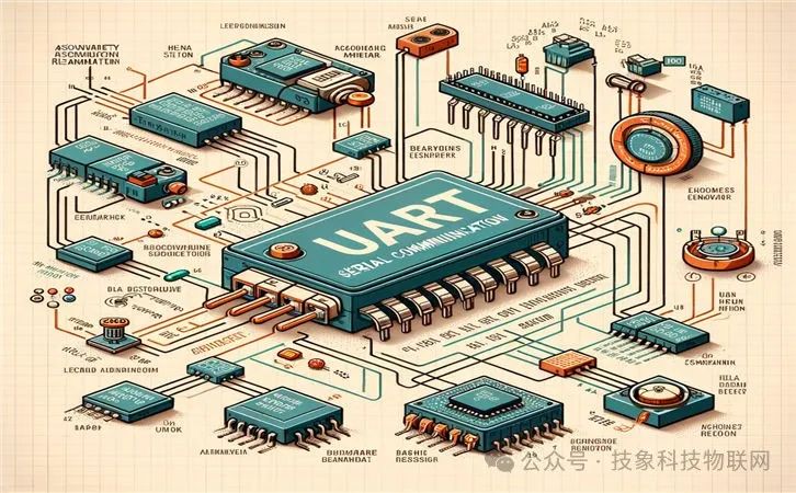
UART (Universal Asynchronous Receiver/Transmitter) is a widely used serial communication protocol in embedded systems. It supports full-duplex communication, allowing simultaneous data transmission and reception, making it very useful in applications that require bidirectional communication. The working principle of UART is to transmit data bit by bit, meaning each binary bit is transmitted independently through signal lines. In the UART communication protocol, a high level typically represents logic ‘1’, while a low level represents logic ‘0’.
The UART protocol supports various data bit configurations, including 5 to 8 data bits, as well as no parity, even parity, and odd parity options. Additionally, the frame is usually terminated with one or two stop bits to ensure correct data reception. The UART protocol also allows the use of different baud rates for data transmission, but the baud rates of the sender and receiver must be close to avoid data errors caused by timing differences. Both ends of the UART devices must also be configured with the same packet structure to enable effective data exchange.
One important feature of the UART protocol is its simplicity. It only uses two independent signal lines (one for sending and the other for receiving) and a clock signal to maintain synchronization between both parties. This design simplifies hardware connections and reduces costs. Although UART is a low-speed communication protocol, it is widely used in various scenarios due to its simple and practical characteristics.
UART is a basic yet powerful serial communication protocol suitable for scenarios requiring simple, efficient, and cost-effective bidirectional communication. By understanding its working principles and configuration parameters, developers can effectively utilize UART for data transmission.
1. What Are the Application Cases of UART Protocol in Different Types of Embedded Systems?
The application cases of the UART protocol in different types of embedded systems include but are not limited to the following:
-
Internet of Things (IoT): UART is widely used for serial communication, as many microcontrollers and microcontroller chips integrate UART hardware modules, simplifying the implementation of serial communication. This indicates that in IoT devices, the UART protocol is used for communication between devices and for data exchange with external systems.
-
Communication Between Embedded Systems: Implementing communication between embedded systems via UART is a typical application scenario. For example, when using multiple BlueFi open-source boards to play a digital solitaire game, UART is involved in inter-system communication.
-
Sensor Data Reading: In embedded systems, UART can be used to read data from sensors. This application case illustrates the practicality of UART in handling real-time data acquisition.
-
UART to CAN Module Applications: In certain specific application scenarios, such as when it is necessary to convert UART protocol to CAN protocol to meet different communication needs, UART to CAN modules are used. This application case demonstrates the flexibility and compatibility of the UART protocol across different communication protocols.
-
Designing Start-Stop Application Layer Protocols: The timing characteristics of UART make it an ideal choice for designing start-stop application layer protocols. This design utilizes the transmission layer functions of UART in the data communication process, further expanding the application range of UART.
The application of the UART protocol in embedded systems is very extensive, ranging from simple device-to-device communication to complex inter-system communication, as well as data acquisition and protocol conversion. These application cases not only showcase the flexibility and efficiency of the UART protocol but also reflect its important position in modern embedded system development.
2. How to Configure UART for High Data Rate and Low Power Consumption?
Configuring UART for high data rates and low power consumption requires understanding the basic working principles and characteristics of UART. UART (Universal Asynchronous Receiver/Transmitter) is a widely used serial communication interface that allows asynchronous communication between devices. When configuring UART, the following aspects need to be considered:
-
Select the Appropriate Baud Rate: The baud rate is an indicator of data transmission speed, typically measured in Baud. To support high data rates, a higher baud rate can be chosen. For example, the UART interface of STM32 can support transmission rates of up to 2Mbps and 4Mbps. However, it is essential to note that the choice of baud rate is also limited by hardware circuit constraints, such as the characteristics of single-ended signal transmission that may limit transmission speed and distance.
-
Utilizing Low Power Modes: To achieve low power consumption, specific low-power UART modes can be utilized. For instance, lpuart allows bidirectional UART communication at limited power consumption, requiring only a 32.768 kHz LSE clock to achieve UART communication at up to 9600 baud/s. When lpuart is driven by a clock source different from LSE, higher baud rates can be achieved. Furthermore, power consumption can be further reduced by setting UARTx_CR1.START to 1, selecting the RXD signal’s start bit determination method as low level, and enabling UART reception.
-
Correctly Configuring Interrupts and DMA: To enhance data transmission efficiency and response speed, DMA (Direct Memory Access) can be employed to read data directly from UART to memory or vice versa. Additionally, correctly configuring interrupts is necessary to process received data or notify the completion of sending promptly. In STM32, the HAL_UART_MspDeInit function can be used to disable UART, release resources, and reduce power consumption.
-
Optimizing Hardware Design: At the hardware level, power consumption can be reduced by minimizing unnecessary signal lines and employing more efficient power management strategies. For example, configuring the Serial Array Unit (SAU) as UART reception and operating in SNOOZE mode is also an effective low-power setup method.
Configuring UART for high data rates and low power consumption requires comprehensive consideration of baud rate selection, the application of low-power modes, correct configuration of interrupts and DMA, and optimization of hardware design. Through these measures, energy consumption can be minimized while ensuring communication efficiency.
3. What Are Common Error Types in UART Communication and Their Solutions?
Common error types in UART communication and their solutions include:
-
Garbling Issues: The primary cause of garbled serial communication is noise interference during data transmission or incorrect baud rate settings. Solutions include ensuring good data line connections, reducing electromagnetic interference, and adjusting baud rates to fit the actual communication environment.
-
Overflow Errors: During data reception, if the RXNE flag is not reset and another character is received, an overflow error occurs. The solution is to check this flag in the interrupt and clear it.
-
Data Loss Issues: Data loss in UART transmission usually occurs due to incomplete transmission. Solutions include using higher precision oscillators to improve clock stability and lowering communication baud rates to reduce data transmission speed, thereby minimizing the possibility of data loss.
-
Cannot Send but Can Receive Issues: First, ensure that the UART pins are correctly connected and that the baud rate is set correctly. Then, check if the buffer is full; if it is, wait for a while until the buffer is free.
-
Common Ground Issues: When encountering serial communication problems, first check the self-test tool, then verify whether both parties share a common ground. GND provides a reference 0 level; if there is no common ground, problems are likely to arise. The solution is to ensure good common ground connections between both parties.
Common errors in UART communication and their solutions cover garbling, overflow, data loss, cannot send but can receive, and common ground issues. By correctly connecting pins, adjusting baud rates, and ensuring common ground connections, these problems can be effectively resolved.
4. How to Implement Error Detection and Correction Mechanisms in UART Communication?
Error detection and correction mechanisms in UART communication can mainly be achieved through the following methods:
-
Parity Bit: By adding a parity bit to the data frame to detect errors during transmission. If the parity bit in the received data frame does not match the calculated parity bit, it indicates that an error occurred during data transmission.
-
Frame Error: Frame errors are detected by checking the start and end flags of the data frame. If the expected start or end flag is not received within the specified time, a frame error is assumed.
-
Retransmission Mechanism: When a data transmission error is detected, the data frame can be retransmitted to attempt to correct the error. This method is suitable for simple error situations but may require additional resources to support retransmission operations.
-
Acknowledgment: After sending a data frame, the sender can wait for an acknowledgment from the receiver. If no acknowledgment is received within a certain time frame, the data frame can be retransmitted. This method can enhance the reliability of data transmission but may increase communication delay.
-
Using More Robust Error Detection and Correction Mechanisms: For complex error situations, such as multi-bit errors, relying solely on parity may not effectively detect or correct errors. In such cases, other advanced error detection and correction techniques, such as Cyclic Redundancy Check (CRC), can be combined.
Error detection and correction mechanisms in UART communication can be implemented through various methods, including but not limited to parity, frame error detection, retransmission mechanisms, acknowledgments, and using more advanced error detection and correction technologies. The choice of mechanism depends on specific application requirements and system resource constraints.
5. What Are the Latest Technological Advances in UART Communication?
The latest technological advances in UART communication can be summarized as follows:
-
Asynchronicity, Simplicity, and Flexibility: The UART serial communication protocol is known for its asynchronicity, simplicity, and flexibility, characteristics that enable it to adapt to different communication needs. This flexibility and adaptability are the foundation for the widespread application of UART in embedded systems, sensor networks, and communication debugging.
-
Importance of Maximum Operating Frequency: The maximum operating frequency of UART is crucial for data transmission rates and system performance. This means that with technological advancements, increasing the operating frequency of UART has become one of the key directions for improving data transmission efficiency and system performance.
-
Integration Trend: With the development of microcontroller technology, UART functionality is increasingly integrated into microcontrollers. For example, Microchip Technology’s PIC16F688T-I/SL integrates UART functionality within the microcontroller. This integration not only reduces the need for external components but also enhances the overall performance and reliability of the system.
-
Enhanced Reliability: To cope with complex communication environments, some vendors refer to UART as Asynchronous Communication Elements (ACE) and provide reliable serial interface solutions based on Universal Asynchronous Receiver/Transmitter. This indicates that enhancing the reliability and stability of UART is an important direction in the latest technological advancements.
The latest technological advances in UART communication mainly focus on increasing its operating frequency to enhance data transmission rates and system performance, as well as reducing the need for external components through integrated design to improve overall system performance and reliability. At the same time, enhancing the reliability and stability of UART is also a significant direction in current technological development.