Communication Requirements and Functions:
The firmware version of V90 is V1.05 and above;
V90 communicates through the RS485 interface at the top of the drive’s front panel (no additional hardware required);
Pin assignment of RS485; (Pin 3 and Pin 8)
Parameters can be modified, such as speed/position/torque set values via ModBus;
Parameters can be monitored, including actual speed/position/torque, fault codes, and alarm codes;
Speed/position control, position/speed set values, control words, and actual position/speed and status words can be sent;
● Unicast mode (address 1 to 31): The master addresses a single slave directly.
● Broadcast mode (address 0): The master addresses all slaves simultaneously.

(Note: Broadcast mode cannot be used for fault requests, as all slaves cannot respond immediately to fault requests.)
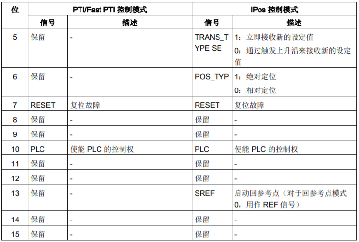
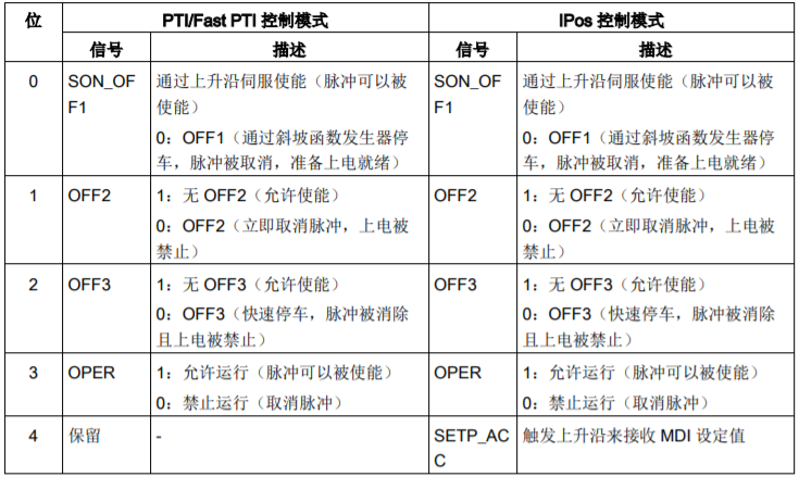
Whether writing control words or receiving status words, it is inseparable from register numbers
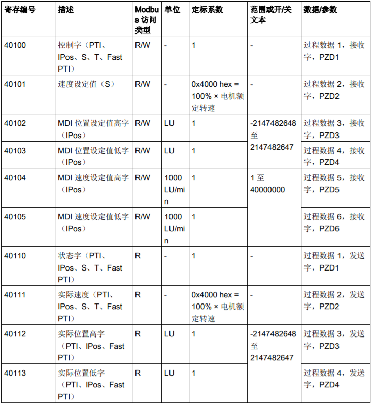
40100 is the most commonly used control word, and 40110 is the most commonly used status word.
In addition, the actual current value, actual torque value, actual speed value, etc. can be read based on the register number.
Once the register number is known, the next step is to choose the control mode for ModBus control.
To recap, we previously discussed the control methods for the V90 pulse sequence, including PTI control, speed control (S), and torque control (T). Which one is the control mode we need?
|
Control Mode |
||||
|
External Pulse Position Control (PTI) |
Internal Set Value Position Control (IPOS) |
Speed Control (S) |
Torque Control (T) |
|
|
Control Word |
||||
|
40100 |
Control Word PTI |
Control Word IPOS |
Control Word S |
Control Word T |
|
40101 |
NA |
NA |
Speed Set Value |
NA |
|
40102 |
NA |
Position Set Value High Word |
NA |
NA |
|
40103 |
NA |
Position Set Value Low Word |
NA |
NA |
|
Status Word |
||||
|
40110 |
Status Word |
Status Word |
Status Word |
Status Word |
|
40111 |
Actual Speed |
Actual Speed |
Actual Speed |
Actual Speed |
|
40112 |
Actual Position High Word |
Actual Position High Word |
NA |
NA |
|
40113 |
Actual Position Low Word |
Actual Position Low Word |
NA |
NA |
(NA: Not applicable)
For example, 40101, speed set value (S), is not effective in PTI, IPOS control, or torque control, and can only be used in speed control mode.
Here’s a question: when we are doing position control (IPOS), in addition to providing the position set value, we also need to provide the speed set value. Why can’t we use 40101 (speed set value S)?
Looking back at the ModBus register mapping table above, 40104 and 40105 are MDI speed set values. Therefore, when we use IPOS (internal position control) mode, its speed set value is not given through 40101, but through 40104 and 40105.
Thus, we can see from the PZD data overview table that the corresponding register numbers vary under different control modes. Here we only listed a part; in the future, we can download the SINAMICS V90 PTI operation manual for reference.
Finally, let’s talk about some precautions:
When the parameter (P29008=1) indicates that the user selects remote control mode, the following signals can be sent to the drive via ModBus; if the parameter (P29008=0), the following signals are controlled using terminal control.
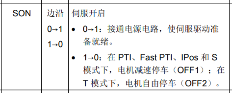
PTI control mode: SON
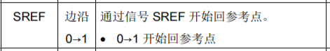
IPOS control mode: SON, SREF (zero return method 0, signal REF)
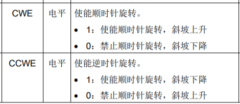
S speed control mode: SON, CWE/CCWE
T torque control: SON
 Internal Digital Input Signals
Different register numbers correspond to different control modes, but not all control modes’ 40100 are the same. The functions achieved are different for different control modes, so even though it is the same 40100, the content of 40100 varies with the selected control mode.
|
Description |
Notes |
|
|
1 |
Set parameterP29004, assignRS485 slave address |
Slave address range1~31 |
|
2 |
Set parameterP29007, select communication protocol type |
P29007 = 0:No protocol P29007 = 1:USS protocol P29007 = 2:MODBUS protocol |
|
3 |
Set parameterP29008, select command source and set source |
P29008 = 1:Remote control mode.PLC will send the MODBUS control word command inPZD format to address R40100. P29008 = 2:Local control mode. The drive is controlled by theDI terminal. |
|
4 |
Set parameterP29009, select baud rate |
5: 4800 baud 6: 9600 baud 7: 19200 baud 8: 38400 baud(default setting) 9: 57600 baud 10: 76800 baud 11: 93750 baud 12: 115200 baud 13: 187500 baud |
|
5 |
Save parameters, restart the drive |
|
|
6 |
Select control mode |
P29003 |
|
7 |
WritePLC program |
EnsurePLC‘s baud rate matches the drive settings. SetPLC parity to even parity. |
|
8 |
Write control word throughPLC, wiring debugging |
Note: When performing loop communication, bit 10 of control word40100 must be set to1, allowing thePLC to control the drive. Meanwhile,0FF2 and0FF3 must be set to1, and edge triggering0FF1 must be used to send theSON signal. |
This chapter ends here, thank you for watching.