What is Modbus?
As the name suggests, it is a bus protocol. For example, serial port protocols, IIC protocols, and SPI are all communication protocols. If you are familiar with such protocols, it is likely that you are in the industrial sector or your product is used in industrial applications.
What is Modbus Used For?
To summarize it in two words: communication.
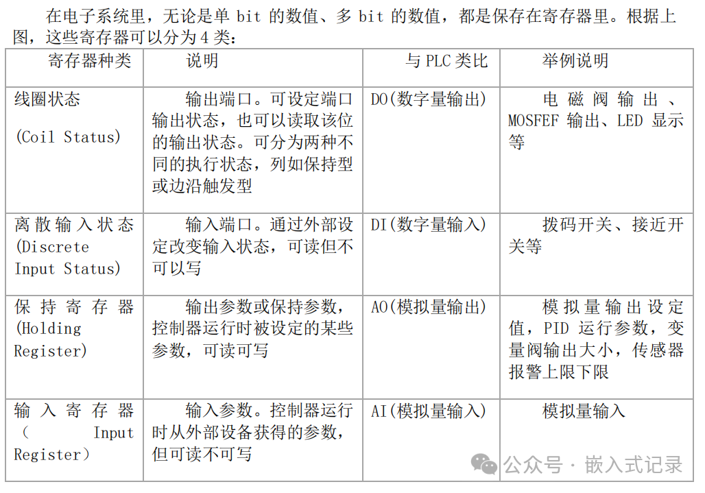
Four Types of Registers
Coil Status (Coil Status) – Read/Write
Discrete Input Status – Read Only
Holding Register – Read/Write
Input Register – Read Only
Protocol Summary
Modbus is a master-slave protocol.
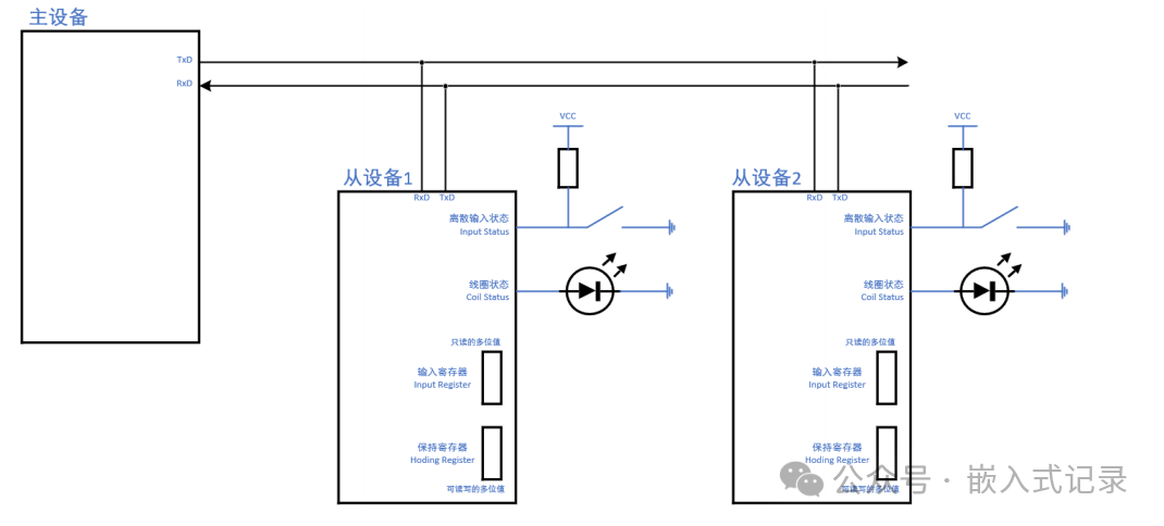
The data sent by the master must contain the following information:
① Device Address: Whether you want to access Slave Device 1 or Slave Device 2
② Which type of register to access, whether to read or write, whether to access one register or multiple registers: this is known as the function code
③ Starting Register Address, Number of Registers: This is defined in the data
④ To ensure the reliability of data transmission, a CRC checksum is also included
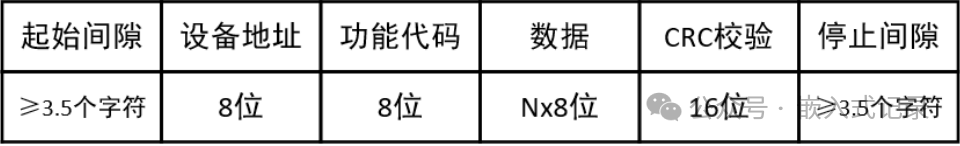
Taking the Modbus RTU protocol as an example, the data packet format sent by the master is as follows:
Function Codes
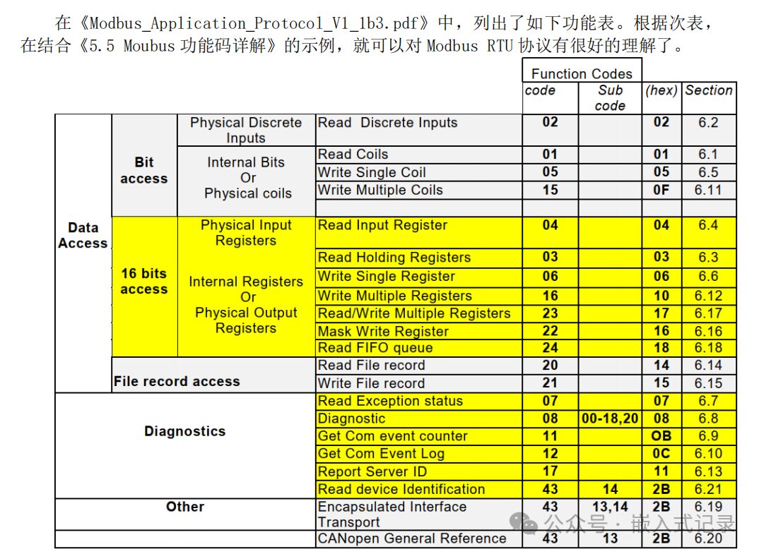
What are the function codes? Common function codes are as follows:
① Read Coil Status (01)
② Read Discrete Input Status (02)
③ Write Single Coil (05), Write Multiple Coils (15)
④ Read Holding Register (03)
⑤ Read Input Register (04)
⑥ Write Single Holding Register (06), Write Multiple Holding Registers (16)
Modbus Message Frame
A message is a frame of data, and a data frame is a message: it refers to a complete set of command data, essentially a string of data.
A Modbus message refers to a frame of data sent from the master to the slave, which includes the slave’s address, the operation the master wants to perform, the checksum, and other content.
The Modbus Protocol RTU message format is as follows:
Frame Structure = Address + Function Code + Data + Checksum
Address: Occupies one byte, range 0-255, with valid range 1-247; others have special purposes, for example, 255 is the broadcast address (the broadcast address responds to all addresses, normally two devices must have the same address to query and respond).
Function Code: Occupies one byte; the meaning of the function code is to know what this instruction is for, for example, you can query the slave’s data or modify data, so different function codes correspond to different functions.
Data: Varies in structure depending on the function code; explanations are provided in subsequent examples.
Checksum: To ensure data accuracy, this is added, and then the previous data is calculated to see if the data is consistent. If consistent, it indicates that this frame of data is correct, and I will respond; if not, it indicates that there was an error in data transmission, so the incorrect data is discarded.
Example Interpretation
Taking (0x01) Read Coil as an example
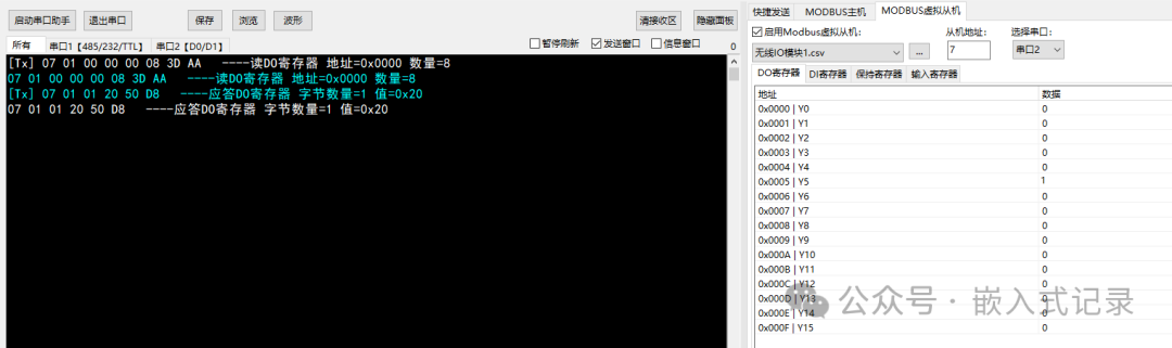
From the example above, the analysis is as follows:
Master sends: 07 01 00 00 00 08 3D AA
Slave responds: 07 01 01 20 50 D8
Analysis:
07 (Slave Device Address) 01 (Function Code) 00 00 (Starting Address 16bit, High Byte First, Low Byte Second) 00 08 (Number of Registers 16bit High Byte First, Low Byte Second) 3D AA (CRC Check)
07 (Slave Device Address) 01 (Function Code) 01 (Data Field Byte Count) 20 (Data 1) 50 D8 (Checksum)
Reference:
https://blog.csdn.net/qq_39400113/article/details/118369506