Three Essential Tools for Modbus Learning
The three essential tools for learning Modbus are ModbusPoll, ModbusSlave, and VSPD, which can facilitate Modbus debugging.
ModbusPoll software is mainly used to simulate a Modbus master station or Modbus client.
ModbusSlave software is primarily used to simulate a Modbus slave station or Modbus server.
VSPD, which stands for Configure Virtual Serial Port Driver, is used to create virtual serial ports on a computer.
Modbus Poll:Modbus master simulator used for testing and debugging Modbus slave devices. This software supports Modbus RTU, ASCII, and TCP/IP. It helps developers test Modbus slave devices or other Modbus protocol tests and simulations. It supports a multi-document interface, allowing simultaneous monitoring of multiple slave devices/data fields. Each window simply sets the slave device ID, function, address, size, and polling interval.Registers and coils can be read and written from any window. If you want to change a single register, simply double-click that value. Alternatively, you can change multiple register/coils values. It provides various data formats, such as float, double precision, and long integer (byte sequence exchange is possible).
Modbus Slave: Modbus slave simulator can simulate up to 32 slave devices/address fields. Each interface provides OLE automation support for EXCEL reports. It is mainly used to simulate Modbus slave devices, receive command packets from the master station, and return data packets. It helps developers of Modbus communication devices simulate and test Modbus communication protocols, used for simulating, testing, and debugging Modbus communication devices. Up to 32 Modbus sub-devices can be simulated in 32 windows. The user interface is the same as Modbus Poll, supporting functions 01, 02, 03, 04, 05, 06, 15, 16, 22, and 23, monitoring serial port data.
Virtual Serial Port Driver 9.0 Virtual COM Port Tool

Using Virtual Serial Port Driver 9.0
Modbus debugging requires two computers to be connected or debugging between a host and a slave. With this tool, you can virtualize two connected COM ports on one computer, allowing debugging to be done on a single computer.
The installation process is straightforward; just keep clicking next, and I won’t elaborate on it here. After installation, open the software, and the main interface is shown below.
We divide it into two parts: the left side is for virtual serial port settings, and the right side is for adding virtual serial ports.
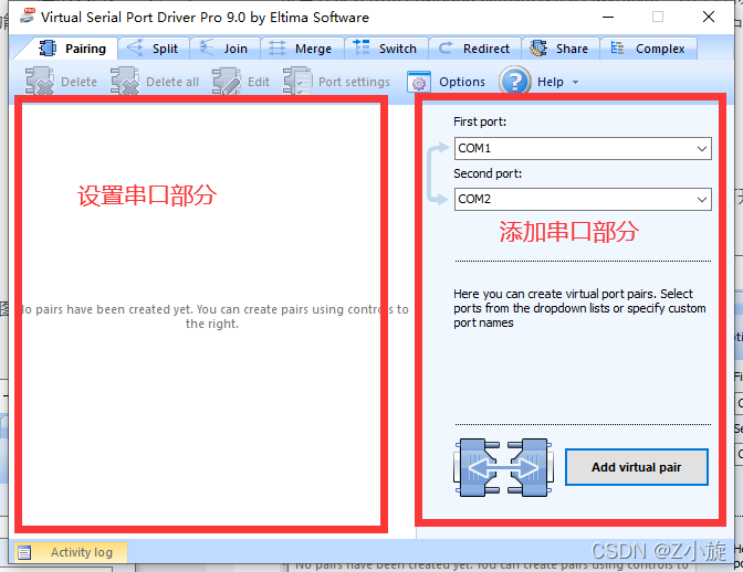
Note that when adding virtual serial ports, try to choose larger COM ports, as smaller COM ports may be occupied by the computer’s keyboard, mouse, USB drive, etc., leading to conflicts.
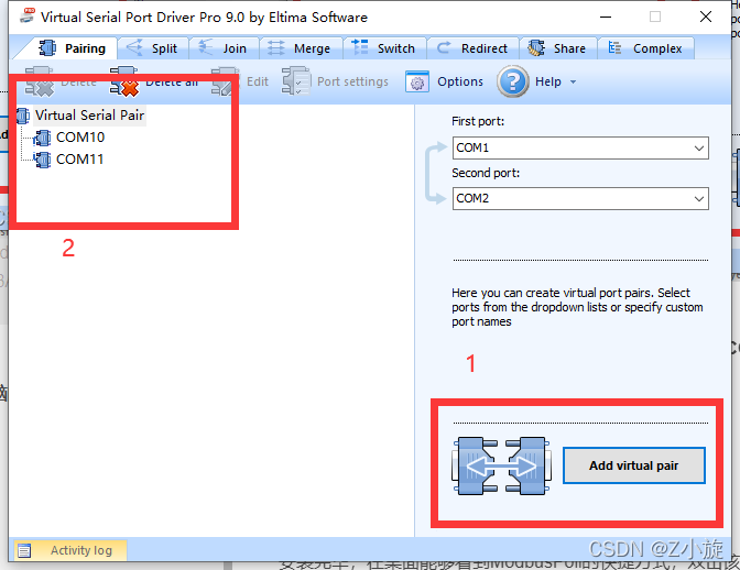
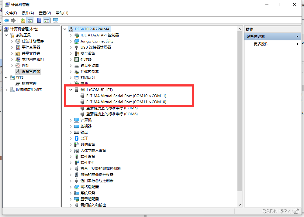
I chose COM10 and COM11. By clicking Add virtual pair, you can see the established virtual serial ports on the left.
In this computer —- right-click —- manage —- device manager -> ports to check if two new ports have been added:
Using Modbus Poll

The installation process is straightforward; just keep clicking next. After installation, crack it (enter a simple key), and the software interface is shown below.
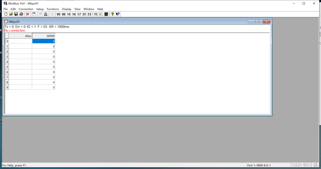
Status Box:
Tx = 0 indicates the number of data frames sent to the master station, which is 0 in the image;
Err = 0 indicates the number of communication errors, which is 0 in the image;
ID = 1 indicates the simulated Modbus sub-device’s device address, which is 1 in the image;
F = 03 indicates the Modbus function code used, which is function code 03 in the image;
SR = 1000ms indicates the sending cycle, once every 1 second.
The red text indicates the current error status; “No Connection” indicates a disconnected status.
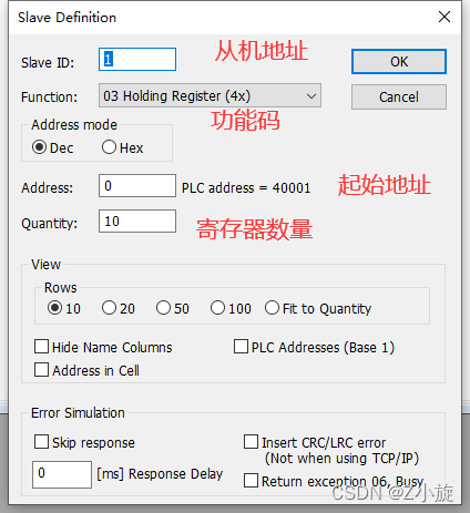
Click Setup —- Read/Write Definition… or press F8 for parameter settings; a parameter setting dialog will pop up.
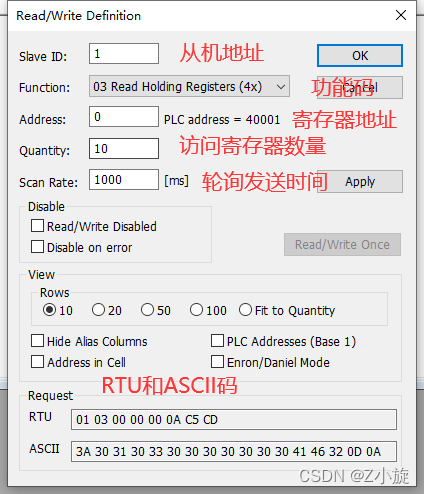
Slave ID is the address of the Modbus slave to access,
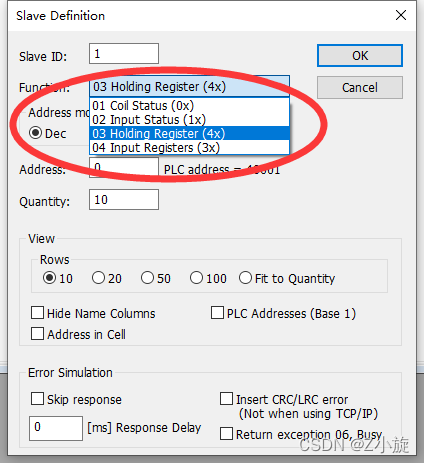
Function is the selection of function code,
Address is the starting address of the register; it varies based on the function code.
Quantity: the number of registers to access,
Scan Rate is the data reading cycle, polling time, in milliseconds,
The Modbus protocol specifies over twenty function codes, but only eight are commonly used for reading and writing storage areas, as shown in the table below:
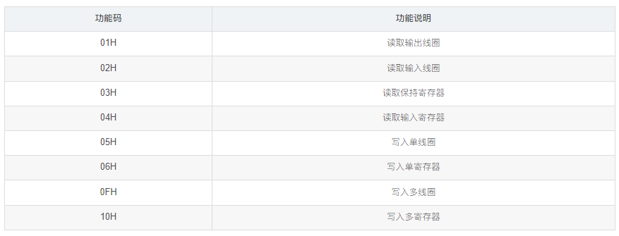
Of course, the most frequently used are 03 and 06, one for reading data and the other for modifying data.
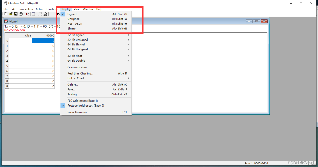
Click Display to set the data display format, defaulting to Signed format (16-bit unsigned binary), with a data range of -32768 to 32767.
Click Connection -> Connect or press “F3” to connect.
Select the virtual COM10 and COM11 ports for the master and slave, respectively. Other options like baud rate 9600, data bits 8, parity bit 1, and stop bit can remain unchanged, then click OK to connect; if the connection fails, a prompt will appear in the second line of the window.
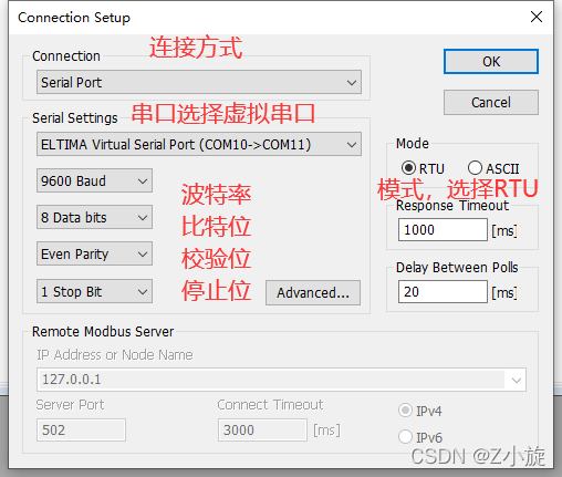
Response Timeout indicates that the slave did not return data within the timeout period, leading to communication failure.
Delay Between Polls is the minimum interval time between each scan, defaulting to 20ms.
Remote Modbus Server indicates the network settings for the terminal slave device in TCP/IP mode.
IP Address indicates the slave’s IP address in TCP/IP mode.
Port indicates the network port of the slave in TCP mode.
Connect Timeout indicates the TCP connection timeout period.
IPV4/IPV6
We will wait for the slave settings to be completed before connecting.
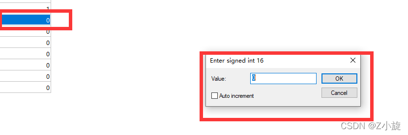
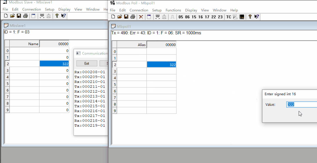
Modify register values (effective for function codes 06 or 16):
Double-click on the register address in the main window to pop up the modification dialog, as shown below:
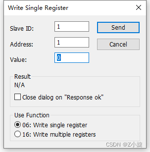
Slave is the address of the Modbus slave.
Address is the address of the register currently being operated on.
Value is the value to be modified, ranging from -32768 to 32767.
Use Function sets the function code, either 06 or 16.
Using Modbus Slave

The installation process is straightforward; just keep clicking next. After installation, crack it (enter a simple key), and the software interface is shown below.
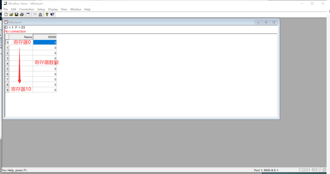
ID indicates the address of the slave.
F indicates the function code.
The lower part shows the register data.
Click Setup —- Slave Definition to set the slave data.
Click Connection -> Connect or press “F3” to connect.
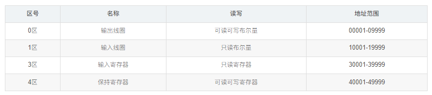
One important difference to note is that the functions for the slave here are four storage areas:
Output coils
Input coils
Holding registers
Input registers
The Modbus protocol defines four storage areas, which are areas 0, 1, 3, and 4, where areas 1 and 4 are readable and writable, while areas 1 and 3 are read-only.
It is basically the same as the master part, so I won’t elaborate further, just remember that if the master selects COM10, the slave must select COM11.
Double-click the slave register data box to modify the register data.
View communication data frames:
Click “Display” —- “Communication” to bring up the serial port send/receive data frame monitoring information dialog box for analyzing the data frames sent and received, as shown below:
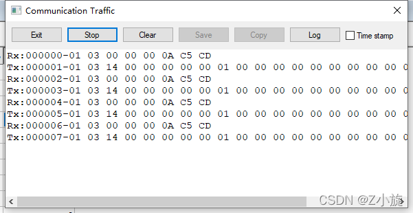
If it is a slave, Rx indicates the received message frame from the master;
Tx indicates the data sent to the master.
We can analyze the data.
1. Master Reading Data from Slave
The message format sent by the master is as follows:
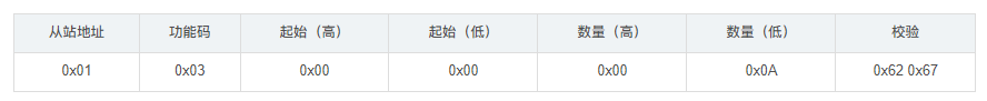
Meaning:
0x01: Slave address
0x03: Query function, reading data from the slave register
0x00 0x00: Represents the starting register address for reading, indicating to start from 0x0000.
0x00 0x0A: The number of registers queried is 0x000A (10). Modbus stores data in registers; by querying registers, different variable values can be obtained. Each register address corresponds to 2 bytes of data; the register address corresponds to the actual storage address of the slave.
0x62 0x67: Cyclic Redundancy Check (CRC).
The slave’s reply message format is as follows:
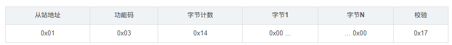
Meaning:
0x01: Slave address
0x03: Query function, reading data from the slave register
0x14: The number of bytes returned is 14.
0x00… 0x00: The value of the register.
0x62 0x67: Cyclic Redundancy Check (CRC).
When the slave modifies the register value, the master’s reception will also change, function code 03.

When the master modifies the register value, the slave’s register value will change, function code 06.
————————————————
Copyright Statement: This article is an original work by CSDN blogger “Z Xiaoxuan”.
Original link: https://blog.csdn.net/as480133937/article/details/123219425