The previous article organized common communication interfaces I (RS232/RS485/USB/TYPE-C principles and differences), and in this article, we continue to organize the principles and differences of CAN, I2C, SPI, UART, and GPIO.
1.CAN Bus Interface
1)Definition
CAN stands for Controller Area Network, developed by the German company BOSCH, known for its research and production of automotive electronic products. It has ultimately become an international standard (ISO 11898) and is one of the most widely used field buses in the world.
CAN belongs to the category of field buses and is a serial communication network that effectively supports distributed control or real-time control. Compared to many distributed control systems based on RS-485, distributed control systems based on CAN bus have significant advantages in the following aspects:
A.Strong real-time data communication between network nodes
B.Short development cycle
C.Established international standard field bus
D.One of the most promising field buses
Compared to general communication buses, CAN bus data communication has outstanding reliability, real-time performance, and flexibility.
2)Applications
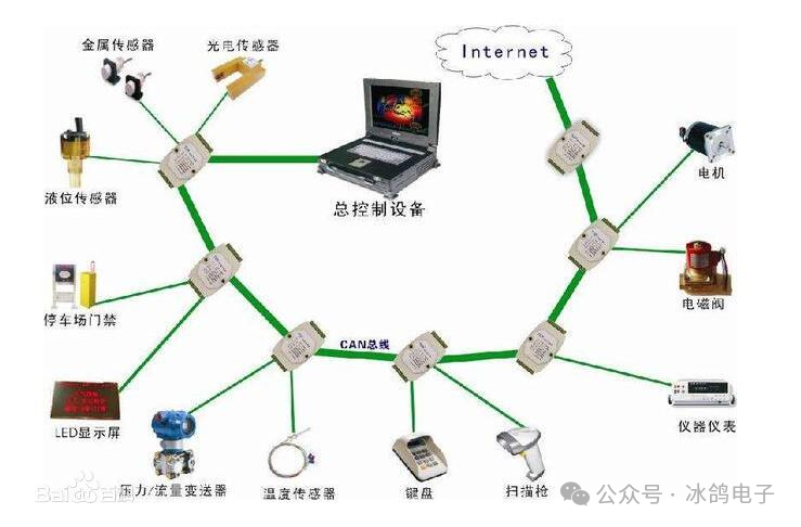
A.CAN bus is a serial data communication protocol developed to solve data exchange between numerous control and testing instruments in modern automobiles. It is a multi-master bus, and the communication medium can be twisted pair, coaxial cable, or optical fiber. The maximum communication rate can reach 1Mbps.
B.A major feature of the CAN protocol is the abolition of traditional station address coding, replaced by coding communication data blocks, allowing the number of nodes in the network to be theoretically unlimited.
C.CAN bus adopts a multi-master competitive bus structure, featuring multi-master operation and decentralized arbitration, as well as broadcast communication. Any node on the CAN bus can actively send information to other nodes at any time without distinction between master and slave, thus enabling free communication between nodes.
D.Simple structure, only 2 wires connected to the outside, and internally integrates error detection and management modules.
E.Characteristics of CAN bus: (1) Data communication has no master-slave distinction; any node can initiate data communication with any other (one or more) nodes, relying on the priority order of information from each node to determine the communication sequence, with high-priority node information communicated in 134μs; (2) When multiple nodes initiate communication simultaneously, lower-priority nodes yield to higher-priority ones, preventing congestion on the communication line; (3) The maximum communication distance can reach 10KM (at rates below 5Kbps), and rates can reach 1Mbps (communication distance less than 40M); (4) The transmission medium for CAN bus can be twisted pair or coaxial cable. CAN bus is suitable for large data volume short-distance communication or long-distance small data volume communication with high real-time requirements, used in multi-master multi-slave or equal node environments.
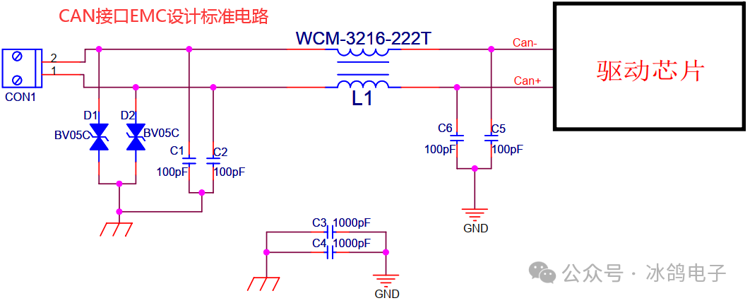
3)EMC Standard Design Circuit
2.I2C Communication
I2C (Inter-Integrated Circuit) bus is a simple, bidirectional two-wire synchronous serial bus developed by Philips.
The I2C bus supports short-distance communication between devices, requiring only two signal lines to complete information exchange.
It transmits data between the two wires through complex logical relationships, with a low communication speed and relatively complex programming. It is used as an interface between processors and some peripheral devices, commonly used in microcontroller systems to connect with small EEPROMs like 24C02.
1)Working Principle
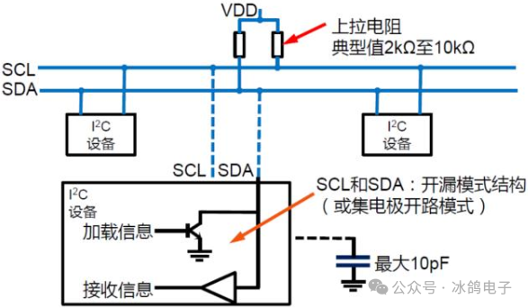
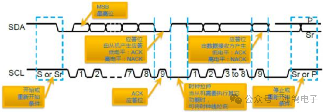
SDA (Serial Data Line) and SCL (Serial Clock Line) are both bidirectional I/O lines, and the interface circuit is open-drain output. They need to be connected to the power supply VCC through pull-up resistors. When the bus is idle, both lines are at a high level, and the external devices connected to the bus are all CMOS devices, with the output stage also being an open-drain circuit. The current consumed on the bus is very small, so the number of devices that can be expanded on the bus is mainly determined by the capacitive load, as each device’s bus interface has a certain equivalent capacitance.
The master device is used to initiate data transmission on the bus and generate a clock to open the transmitting devices. At this time, any addressed device is considered a slave device. The relationship between master and slave, sender and receiver on the bus is not constant but depends on the direction of data transmission at that moment. If the master wants to send data to the slave device, the master first addresses the slave device, then actively sends data to the slave device, and finally terminates the data transmission; if the master wants to receive data from the slave device, the master first addresses the slave device, then receives the data sent by the slave device, and finally terminates the receiving process. In this case, the master is responsible for generating the timing clock and terminating the data transmission. Data transmission and address setting are very flexible and set by software.
2)Main Features of I2C
A.Simple bidirectional two-wire bus (open-drain mode):
B.Serial Data (SDA) and Serial Clock (SCL)
C.Multi-master bus with arbitration capability
D.Each device on the bus has a different identification address
E.Each data transmission is initiated by the master, and the clock is always provided by the master
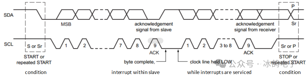
3)The master device reads data from the slave device, as shown in the figure below
|
• Master writes to slave (7-bit address) |
||||||||||
|
S/Sr |
7bits Address |
1bit W(0) |
1bit ACK |
8bits Data |
1bit ACK |
— |
— |
8bits Data |
1bit NACK |
Sr/P |
|
• Master reads from slave (7-bit address) |
||||||||||
|
S/Sr |
7bits Address |
1bit R(0) |
1bit ACK |
8bits Data |
1bit ACK |
— |
— |
8bits Data |
1bit NACK |
Sr/P |
SCL is the clock, and SDA carries the data. When SDA changes from 1 to 0 while SCL is still 1, it indicates the start of data transmission. The next 7 bits are the device address. Following that is the read/write flag, which is 1 for reading and 0 for writing. If there is a device on the I2C bus corresponding to the requested address, the slave device will send an ACK signal to notify the master device that it can send data. After receiving the ACK signal, the master device sends an 8-bit data. Once the transmission is complete, SCL remains at 1, and SDA changes from 0 to 1, indicating the end of transmission.
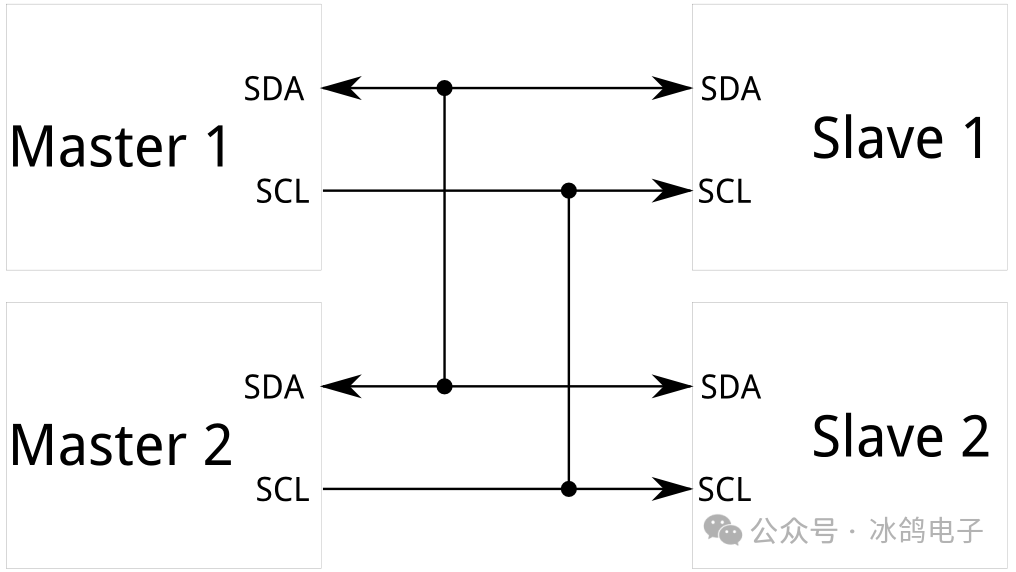
4)Master-Slave Device Communication
The master refers to the device that initiates data transmission and generates the clock signal on the bus to drive that transmission, while the addressed devices act as slaves.
Unlike SPI, I2C supports a multi-master system, allowing multiple masters to communicate with all slaves (masters cannot communicate with each other via I2C, and each master can only use the I2C bus in turn).
I2C data transmission rates are between serial and SPI, with most I2C devices supporting 100KHz and 400KHz modes. Using I2C for data transmission incurs some overhead: for every 8 bits of data sent, an additional 1 bit of metadata (ACK or NACK) is required. I2C supports bidirectional data exchange, and since there is only one data line, communication is half-duplex.
3.SPI Communication
1)Definition:
SPI stands for Serial Peripheral Interface. It is a synchronous serial interface technology introduced by Motorola, characterized by high speed, full-duplex communication, and synchronization. It occupies only four pins on the chip, saving pin space. SPI interfaces are generally used for high-speed data communication between internal components of products, commonly applied in EEPROM, FLASH, real-time clocks, AD converters, as well as between digital signal processors and digital signal decoders.
2)Advantages and Disadvantages
● Advantages: Supports full-duplex communication, simple communication, and fast data transmission rates.
● Disadvantages: Lacks specified flow control and acknowledgment mechanisms to confirm data reception, which presents certain reliability issues compared to I2C bus protocols.
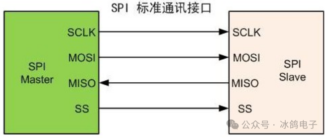
3)Protocol Communication Timing DetailsA. SPI Communication Method
The communication principle of SPI is straightforward; it operates in a master-slave mode, typically involving one master device and one or more slave devices, requiring at least four lines (in fact, three can suffice for unidirectional transmission). The common lines for all SPI-based devices are SDI (Data Input), SDO (Data Output), SCLK (Clock), and CS (Chip Select). ①SDO/MOSI – Master device data output, slave device data input, corresponding to MOSI master output slave input②SDI/MISO – Master device data input, slave device data output, corresponding to MISO master input slave output③SCLK – Clock signal generated by the master device; ④CS/SS – Slave device enable signal controlled by the master device.
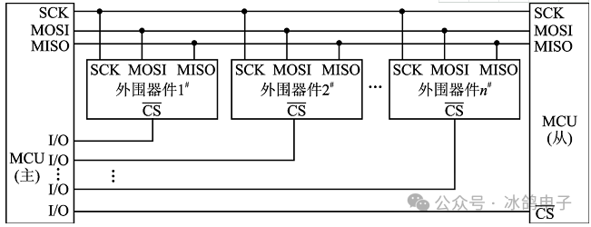
When there are multiple slave devices, each slave device has a chip select pin connected to the master device. When our master device communicates with a specific slave device, it needs to pull the corresponding chip select pin low or high.
CS: The CS signal controls whether the chip is selected, meaning that operations on this chip are only valid when the chip select signal is at the predetermined enable level (high or low), allowing multiple SPI devices to be connected on the same bus.
SDI/SDO/SCLK: Communication is completed through data exchange. It is important to note that SPI is a serial communication protocol, meaning data is transmitted bit by bit. This is why the SCK clock line exists; it provides clock pulses, and SDI and SDO complete data transmission based on these pulses. Data output occurs through the SDO line, with data changing on the rising or falling edge of the clock, and being read on the subsequent falling or rising edge. Completing one bit of data transmission follows the same principle. Thus, at least 8 clock signal changes (one rising and one falling edge count as one) are required to complete the transmission of 8 bits of data.
B. SPI Communication Description
There are four different modes for SPI communication; different slave devices may be factory-set to a specific mode, which cannot be changed. However, both communicating parties must operate in the same mode, so we can configure the SPI mode of our master device through CPOL (Clock Polarity) and CPHA (Clock Phase) to control the communication mode of our master device, as follows:
Mode0: CPOL=0, CPHA=0
Mode1: CPOL=0, CPHA=1
Mode2: CPOL=1, CPHA=0
Mode3: CPOL=1, CPHA=1
Note:Our master device can control the clock, as SPI communication does not have dedicated communication cycles, start signals, or end signals like UART or IIC communication; thus, our SPI protocol can control the clock signal line, which remains either high or low when there is no data exchange.
4.UART Module
Universal Asynchronous Receiver/Transmitter (UART) is commonly referred to as UART;
UART is a general serial data bus used for asynchronous communication. It is part of computer hardware. It converts data to be transmitted between serial and parallel communication. As a chip that converts parallel input signals into serial output signals, UART is usually integrated into other communication interfaces.
The bus supports bidirectional communication, enabling full-duplex transmission and reception. In embedded design, UART is used for communication between the host and auxiliary devices, such as communication between car audio and external AP, and communication with PCs including monitoring debuggers and other devices like EEPROM.
1)Principle
UART is a chip that converts parallel input into serial output, usually integrated on the motherboard, most commonly the 16550AFN chip. Since computers use parallel data internally, data cannot be sent directly to the modem; it must be organized by UART for asynchronous transmission. The process is as follows: the CPU first places the data to be written to the serial device into the UART register (temporary memory block), and then transmits it to the serial device through FIFO (First Input First Output). If there is no FIFO, the information will become disordered and cannot be sent to the modem.
2)UART Communication
UART first converts the received parallel data into serial data for transmission. The message frame starts with a low start bit, followed by 7 or 8 data bits, an optional parity bit, and one or more high stop bits. When the receiver detects the start bit, it knows that data is ready to be sent and attempts to synchronize with the sender’s clock frequency. If parity is selected, UART adds a parity bit after the data bits to assist with error checking.
During reception, UART removes the start and stop bits from the message frame, performs parity checking on the incoming bytes, and converts the data bytes from serial to parallel. UART also generates additional signals to indicate the status of sending and receiving.
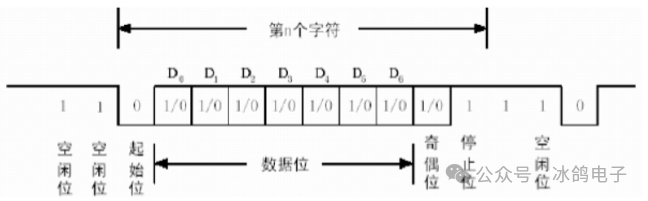
Since UART is asynchronous transmission, there is no synchronous clock for transmission. To ensure the correctness of data transmission, UART uses a clock that is 16 times the data baud rate for sampling. Each data bit has 16 clock samples, taking the middle sample value to ensure that sampling does not slip or misread. Generally, the number of data bits in a UART frame is 8, so even if there is a one-clock error, the receiving end can correctly sample the data.
3) UART and COM
In embedded systems, the term serial port generally refers to the UART port. In fact, UART and COM refer to the physical interface form (hardware), while TTL and RS-232 refer to the voltage standards (electrical signals).
UART has 4 pins (VCC, GND, RX, TX), using TTL levels, where low level is 0 (0V) and high level is 1 (3.3V or above).
COM port is the commonly used port on desktop computers (as shown below), with 9 pins, using RS232 levels, which is negative logic level, defining +5~+12V as low level and -12~-5V as high level.
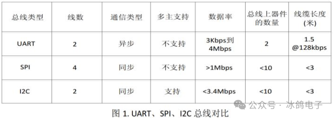
5.Comparison of SPI, I2C, and UART Serial Buses
1)Concept Definition
SPI (Serial Peripheral Interface); I2C (INTER IC BUS: meaning bus between ICs) UART (Universal Asynchronous Receiver Transmitter)
2)Communication Method
SPI and UART can achieve full-duplex, but I2C cannot;
3)Other Differences
A.I2C has fewer lines, which I think is more powerful than UART and SPI, but technically it is also more complicated because I2C requires support for bidirectional I/O and uses pull-up resistors, which I think has weaker anti-interference capability, generally used for communication between chips on the same board, and less for long-distance communication. SPI is simpler to implement, while UART requires a fixed baud rate, meaning the intervals between two data bits must be equal, while SPI does not have this requirement because it is a clocked protocol.
B.I2C is slightly slower than SPI, the protocol is a bit more complex, but it requires fewer connections than standard SPI.
6.GPIO Interface
1)GPIO Concept
GPIO (General Purpose I/O Ports) refers to general input/output ports, similar to P0—P3 of the 8051, typically providing a “general programmable I/O port” on embedded microprocessors, that is GPIO.In simpler terms, these are some pins that can output high or low levels or read the pin status—whether it is high or low.
A GPIO port requires at least two registers: one for control, the “General IO Port Control Register,” and another for storing data, the “General I/O Port Data Register.” Each bit of the data register corresponds to a GPIO hardware pin, and the data flow direction is set through the control register, which can set the data direction for each pin.
Users can interact with hardware through GPIO ports (such as UART), control hardware operation (such as LEDs, buzzers, etc.), and read hardware status signals (such as interrupt signals). The use of GPIO ports is very widespread.
2)Advantages of GPIO (Port Expander):
1. Low power consumption: GPIO has lower power consumption (about 1μA, while μC operating current is 100μA).
2. Integrated IIC slave interface: GPIO has a built-in IIC slave interface, allowing it to work at full speed even in standby mode.
3. Small package: GPIO devices offer the smallest package size—3mm x 3mm QFN!
4. Low cost: You do not pay for unused features.
5. Fast time to market: No need to write additional code, documentation, or maintenance work.
6. Flexible light control: Built-in multiple high-resolution PWM outputs.
7. Pre-determined response time: Shorten or determine the response time between external events and interrupts.
8. Better lighting effects: Matched current output ensures uniform display brightness.
9. Simple wiring: Only 2 wires are needed to form an IIC bus or 3 wires to form an SPI bus.
10. Similar functionality to several GPIO pins of ARM, GPxCON controls pin functions, GPxDAT is used for reading and writing pin data. Additionally, GPxUP determines whether to use pull-up resistors. x can be A, B, H/J.
11. GPAUP has no pull-up resistor.