
OTA upgrades are no longer a novelty; most IoT terminal devices now have this capability.
Today, I will share the detailed process of OTA upgrades using the AT32 as an example.
Over-the-Air Technology (OTA) allows users to write to specific areas of User Flash while their programs are running, enabling easy updates of firmware after product release through a reserved communication port.
To implement OTA functionality, two project codes need to be written during firmware design: the first project is for the Bootloader area, and the second project is the App code, which contains the actual functional code for execution and upgrades. Both project codes are simultaneously written to User Flash.
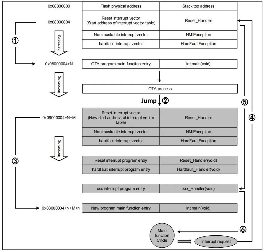
Figure 1. OTA Code Execution Process
2) The interrupt vector table of the App program must be appropriately moved, with the offset being x.
Quick Start Method for AT32 USART OTA
-
Indicator LEDs LED2/LED3/LED4 -
USART1 (PA9/PA10) -
AT-START Experimental Board
1) tool_release
-
IAP_Programmer.exe, a PC tool for demonstrating the OTA upgrade process
-
Bootloader, Bootloader source program for running LED2 blinking -
App_led3_toggle, App1 source program for running LED3 blinking -
App_led4_toggle, App2 source program for running LED4 blinking
Note: The project is based on Keil v5. If users need to use it in other compilation environments, please refer to the corresponding BSP directory AT32F403A_407_Firmware_Library_V2.x.x\project\at_start_f403a\templates for modifications.
Using OTA Demo
This document describes two common OTA application demos, the template app and dual app, which will be introduced in the following chapters.
3) Select the correct serial port, APP download address, and bin document, then click Download as shown below.
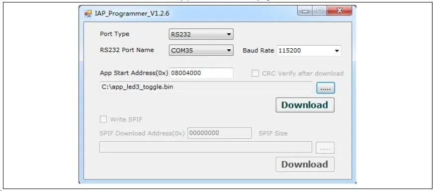
Figure 2. IAP demo on the host computer
Address Distribution
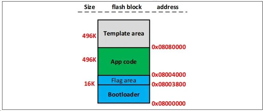
Figure 3. Flash Address Allocation
Execution Process
OTA consists of three parts: Bootloader, App, and Template, with the application executed in the App. The overall process flow diagram is as follows:
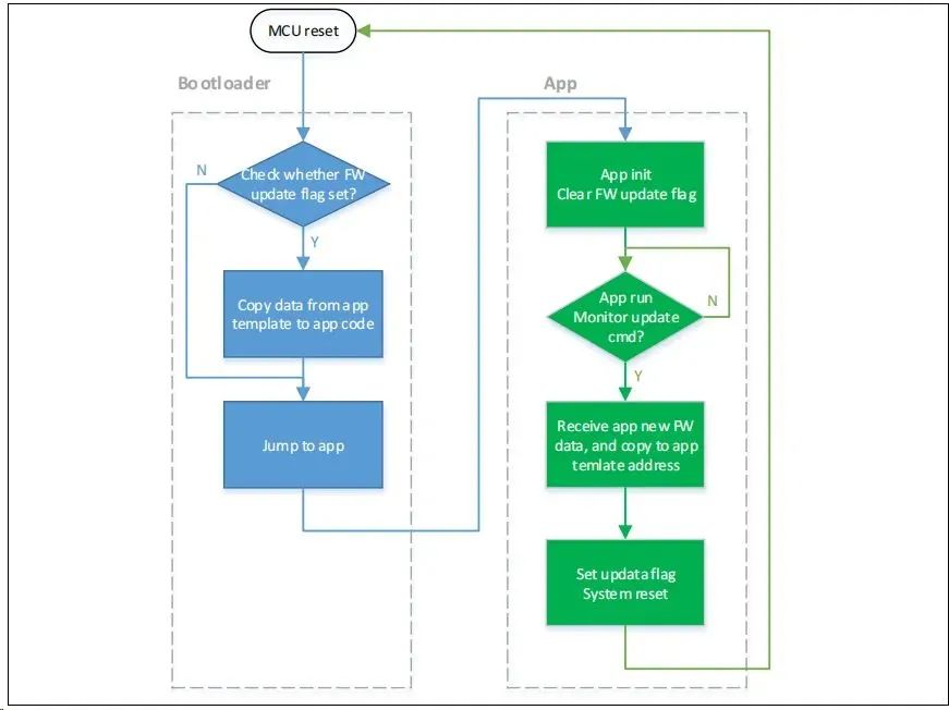
Figure 4. Program Execution Process
Bootloader Project Settings
1) Keil Settings
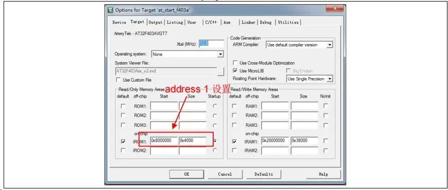
Figure 5. Address 1 Settings in Bootloader Project in Keil
2) Modify the Bootloader Source Code in the ota.h File
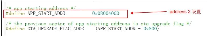
Figure 6. Address 2 Settings in Bootloader Project
App Project Settings
The OTA demo provides two App programs for testing, both starting at address 2 (0x800 4000). App1 blinks LED3, and App2 blinks LED4. Taking App1 as an example, the design steps are as follows:
1) Keil Project Settings
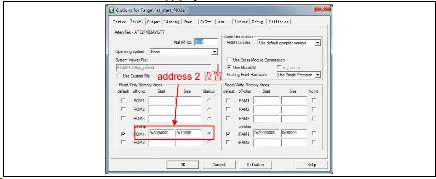
Figure 7. Address 2 Settings in App Project in Keil
2) App1 Source Program Settings
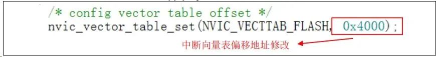
Figure 8. Vector Table Offset Settings in App Project
3) Compile to Generate bin File
Through the User tab, set to call fromelf.exe after compilation to generate a .bin file from the .axf file for OTA updates. By following these three steps, we can obtain a .bin APP program, which can be updated through the Bootloader program.
-
First, download the Bootloader project -
Then debug the App project
Address Distribution
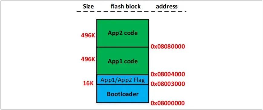
Figure 9. Flash Address Allocation
Note: The last two sectors of the Bootloader area are used to store flags indicating whether the App is functioning correctly. Users must ensure not to overwrite the flag’s address when compiling and modifying the Bootloader.
Execution Process
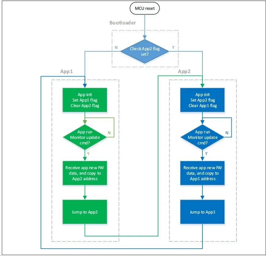
Figure 10. Program Execution Process
Bootloader Project Settings
1) Keil Settings
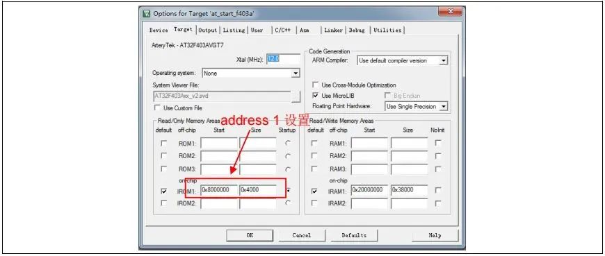
Figure 11. Address 1 Settings in Bootloader Project in Keil
2) Modify the Bootloader Source Code in the ota.h File
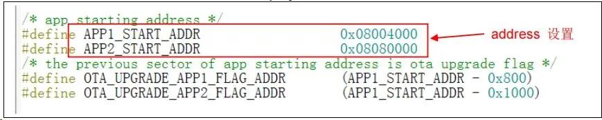
Figure 12. Address 2 Settings in Bootloader Project
App Project Settings
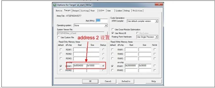
Figure 13. Address 2 Settings in App Project in Keil
2) App1 Source Program Settings
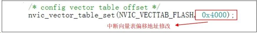
Figure 14. Vector Table Offset Settings in App Project
3) Compile to Generate bin File
Through the User tab, set to call fromelf.exe after compilation to generate a .bin file from the .axf file for OTA updates. By following these three steps, we can obtain a .bin APP program that can be updated through the Bootloader program.
4) Enable Debug App Code Functionality
If debugging of the App project is required during the design of the App code, please follow these operations.
-
First, download the Bootloader project -
Then debug the App project
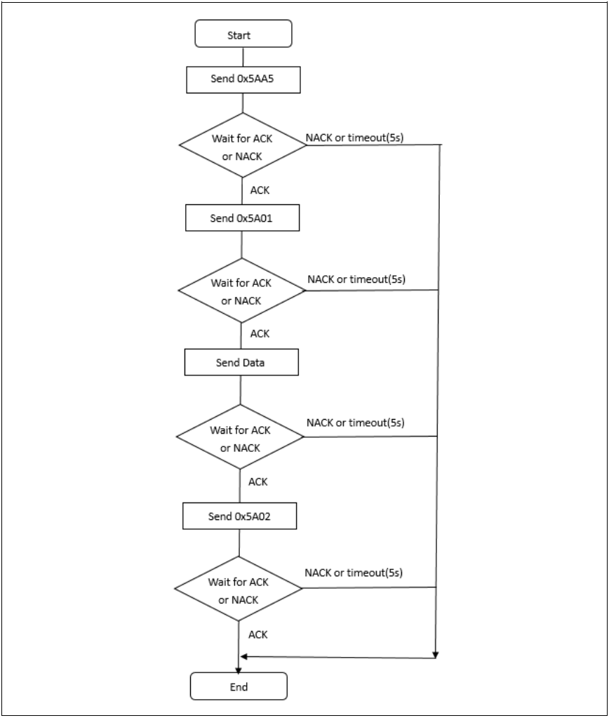
Figure 15. Host Communication Protocol
2) Embedded Side Communication Protocol

Figure 16. Embedded Side Communication Protocol
Checksum: 1byte, the low eight bits of the checksum for the 4bytes Addr + 2KBytes data
This document is sourced from the internet, freely conveying knowledge, and the copyright belongs to the original author. If there are copyright issues, please contact me for deletion.
Notice
Due to recent changes in WeChat official account push rules, to prevent missing articles, you can star it to keep it on top, so that every article pushed will appear in your subscription list.
You may also like:
Easy to Understand | Step-by-Step Guide to Writing Your First Host Computer
General Library for Differential Upgrades Suitable for Embedded Systems!
Sharing a Highly Flexible Protocol Format (with Code Example)
Sharing Several Practical Code Snippets (Second Edition)
Sharing a Bug Localization Method You Might Not Know
Sharing a Method for Modifying Configuration Files
Embedded Miscellaneous Weekly Journal Issue 13: lz4
Embedded Parallel Multithreading Processors, Take a Look!
Reply 1024 in the WeChat official account chat interface to obtain embedded resources; reply m to view article summaries