Introduction
Recently, I shared the PCBA of Bosch’s second-generation water pump, which seemed to be quite popular. Interested friends can click the link below to go directly to it.Comparison of New and Old Generations of Bosch Automotive Electronic Water Pump PCB
I happen to have a blower board that I obtained from the second-hand market. This is a Bosch three-phase BLDC blower board, and based on the datacode, it doesn’t seem to be an early design, so I am sharing it with everyone.
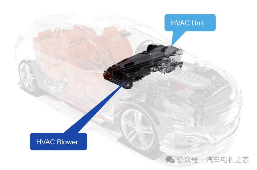
Function of Automotive Blower
The automotive blower is an important component of the vehicle’s air conditioning system, responsible for circulating air through the air conditioning system’s ducts to achieve cooling, heating, and ventilation inside the vehicle. As shown in the figure below, this is a typical air conditioning system, where the HVAC Blower is the blower. Its position is quite close to the passengers and the driver’s cabin.
The blower motor mainly comes in two types: brushed DC (BDC) and three-phase brushless DC (BLDC). Brushed blowers, also known as speed controllers, are still widely used; however, BLDC motors are gradually becoming mainstream due to their high efficiency, long lifespan, low mechanical noise, and high EMC levels.
Design Specifications
For a three-phase BLDC system designed for 12V, the simplified design specifications are as follows:
1) Voltage range: 9V to 16V;
2) Power typically ranges from 200W to 400W;
3) Speed generally ranges from about 800rpm to 4000rpm;
4) Speed control using PWM or LIN;
5) Requires both forward and reverse airflow functions;
6) Noise must be low across the entire operating range, including during startup, operation, and shutdown;
Challenges
For three-phase BLDC blowers, there are mainly two challenges:
1) The noise requirements for the system are particularly high. This high requirement is not only about meeting decibel levels but also ensuring that the subjective experience of sound is comfortable, meaning that the sounds of different frequencies should be relatively harmonious without any particular frequency being overly prominent, and the sound scale curve should be relatively close across speeds. Additionally, if a single resistor is used to achieve this, it becomes even more challenging.
2) EMC is another challenge; pursuing Level 4 and Level 5 will be very demanding.
Solution Analysis
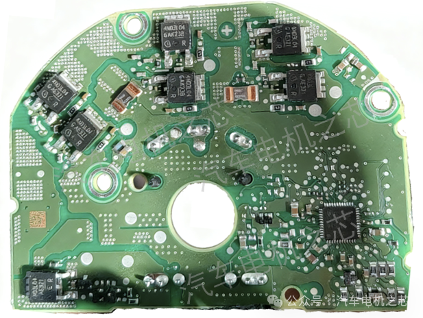
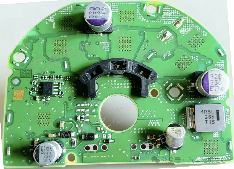
The board I have on hand comes from the second-hand market and is said to be a Bosch blower board.
Let’s start with a front view.
Now, a back view.
Main chip list:
TLE9879QXA40 + IPD70N03S4L-04 * 7 + 2-channel OPA
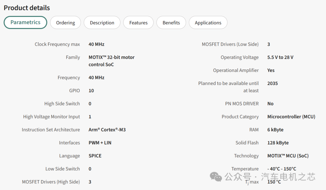
1) The TLE9879 is an Infineon smart pre-driver motor control SOC chip, with Flash memory that is twice as large as that of the TLE9877, as shown in the figure below.
Thanks to the high integration of the TLE9879, the overall design of this blower PCBA is quite simple.
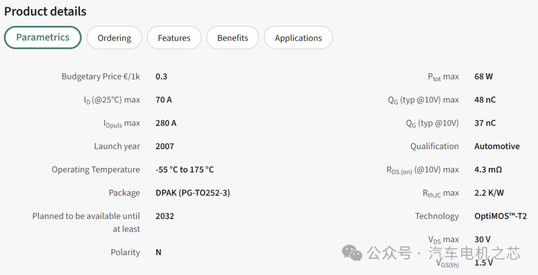
2) There are a total of 7 MOSFETs, one for reverse polarity protection and six for three-phase bridge driving. The parameters of the MOSFETs are shown in the figure below. It seems that a 30V rated, 4.3 milliohm resistance MOSFET was chosen, possibly due to cost considerations.
3) It should be noted that the external 2-channel OPA is used for dual-resistor sampling, as the TLE9879 only has one internal operational amplifier.
This detail shows that if one wants to solve the noise issue, using a single resistor will face significant challenges. This is why we see that many blower designs mostly adopt dual-resistor solutions. However, it should be pointed out that there are currently mass-produced single-resistor solutions, such as ELMOS’s E523.06, which is a single-resistor solution.
Of course, creating a good blower solution involves not only noise but also many other detailed issues that need to be tackled, but noise is the most challenging part. That’s all for today; for technical exchanges regarding blowers, feel free to message me for my WeChat ID or group number.