Follow “Jicheng Training”, focused on automation education for 14 years

Common input devices for PLC include buttons, limit switches, proximity switches, toggle switches, dip switches, and various sensors, while output devices include relays, contactors, and solenoid valves. Correctly connecting the input and output circuits is a prerequisite for ensuring the safe and reliable operation of the PLC.
01Connecting PLC with Control Equipment
Figure 1 shows the wiring diagram for connection with control equipment input devices such as buttons, limit switches, and toggle switches. The PLC in the figure uses a DC common point input, meaning all input points share a common terminal COM, which is also connected to a DC24V power supply. For grouped inputs, refer to the method shown in the figure below for grouped connections.
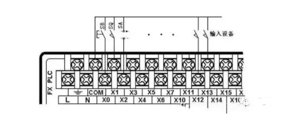
▲Figure 1 Connection of PLC with Control Equipment Input Devices
02Connecting PLC with Rotary Encoders
A rotary encoder is an optical rotary measurement device that directly converts the measured angular displacement into digital signals (high-speed pulse signals). Therefore, the output pulse signal from the rotary encoder can be directly input to the PLC, using the PLC’s high-speed counter to count the pulse signals to obtain measurement results. Different models of rotary encoders have different numbers of output pulses; some output A, B, and Z phase pulses, while others only output A and B phases, and the simplest only outputs the A phase.
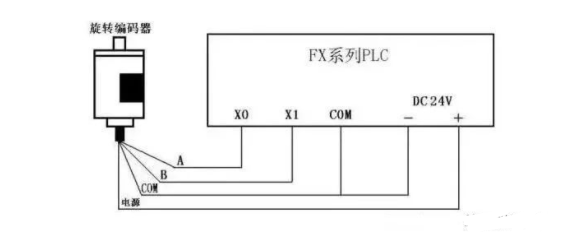
▲Figure 2 Connection of Rotary Encoder with PLC
As shown in Figure 2, this is a connection diagram for a two-phase pulse output rotary encoder with the FX series PLC. The encoder has four wires: two are pulse output lines, one is the COM terminal line, and one is the power line. The encoder can be powered by an external power supply or directly use the PLC’s DC24V power supply. The power “-” terminal should be connected to the encoder’s COM terminal, while the “+” connects to the encoder’s power terminal. The encoder’s COM terminal connects to the PLC input COM terminal, and the A and B phase pulse output lines connect directly to the PLC input terminals, taking care to note the PLC input response time. Some rotary encoders also have a shielding wire, which should be grounded during use.
03Connecting PLC with Sensors
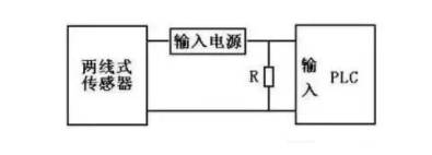
There are many types of sensors, and their output methods vary. When using two-wire sensors like proximity switches and photoelectric switches, due to the high leakage current of the sensors, incorrect input signals may occur, leading to erroneous operations of the PLC. In this case, a bypass resistor R can be connected in parallel at the PLC input terminal, as shown in Figure 3. If the leakage current is less than 1mA, its impact can be ignored.
In the formula: I is the sensor’s leakage current (mA), UOFF is the upper limit of the PLC input voltage low level (V), and RC is the PLC’s input impedance (KΩ), which varies depending on the input point.
04Connecting PLC with Multi-position Dip Switches
If certain data in the PLC control system needs to be frequently modified, multi-position dip switches can be used to connect with the PLC for external data setting. As shown in Figure 4, this is a schematic diagram of a single dip switch, which can input a decimal number from 0 to 9 or a hexadecimal number from 0 to F.
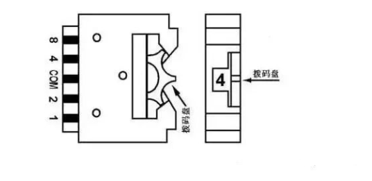
▲Figure 4 Schematic Diagram of a Single Dip Switch
As shown in Figure 5, four dip switches are assembled together, connecting the COM terminals of each dip switch to the COM terminal on the PLC input side. The four data lines of each dip switch are connected to four input points on the PLC in a specific order. As can be seen from the figure, using dip switches will occupy many PLC input points, so it is generally not advisable to adopt this method unless absolutely necessary.
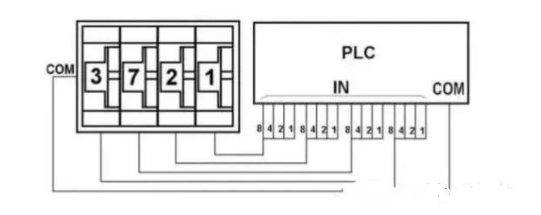
▲Figure 5 Connection of 4-position Dip Switch with PLC
05Connecting PLC with Output Devices
When connecting the PLC with output devices, the voltage type and level of the corresponding output devices (loads) can differ between different groups (different common terminals), but for output points within the same group (same common terminal), the voltage type and level should be the same. The decision to group connections should depend on the voltage type and level of the output devices. As shown in Figure 6, using FX2N as an example, the connection method between the PLC and output devices is illustrated. The connection shown assumes that the output devices have the same power supply, so the common terminals of each group are connected together; otherwise, they should be grouped separately. The figure only shows the connection of output points Y0-Y7 with output devices, and the connection method for other output points is similar.
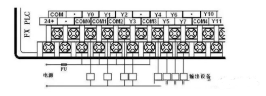
▲Figure 6 Connection of PLC with Output Devices
06Connecting PLC with Inductive Loads
The PLC output terminal is often connected to inductive output devices (inductive loads). To suppress the voltage generated when the inductive circuit is disconnected, which could damage the internal output components of the PLC, when connecting the PLC with inductive output devices, if it is a DC inductive load, a freewheeling diode should be connected in parallel across its terminals; if it is an AC inductive load, a resistor-capacitor absorption circuit should be connected in parallel across its terminals, as shown in Figure 6-10.
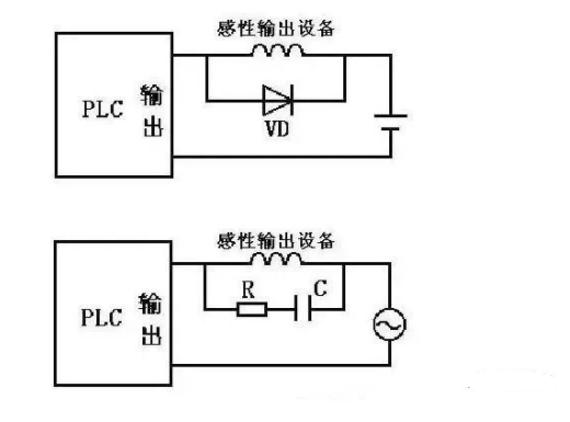
▲Figure 7 Connection of PLC with Inductive Output Devices
In the figure, the freewheeling diode can be selected with a rated current of 1A and a rated voltage greater than three times the supply voltage; the resistance value can be taken as 50~120Ω, and the capacitance value can be taken as 0.1~0.47μF, with the rated voltage of the capacitor being greater than the peak voltage of the supply. When wiring, be sure to pay attention to the polarity of the freewheeling diode.
07Connecting PLC with Seven-Segment LED Display
The PLC can be directly connected to the seven-segment LED display with switch outputs, but if the PLC controls multiple seven-segment LED displays, many output points are required.
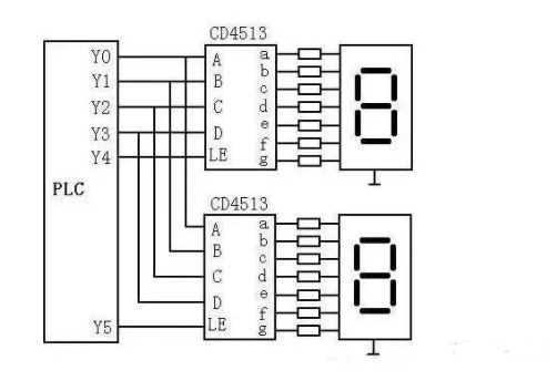
▲Figure 8 Connection of PLC with Two-Digit Seven-Segment LED Display
As shown in Figure 8, in the circuit, a chip CD4513 with latching, decoding, and driving functions drives the common cathode LED seven-segment display. The data input terminals A to D of the two CD4513 chips share four output terminals of the PLC, where A is the least significant bit and D is the most significant bit. LE is the latch enable input terminal, which latches the BCD number input at the data input terminals into the internal register of the chip on the rising edge of the LE signal and displays the number after decoding. If the input is not a decimal number, the display will turn off. When LE is high, the displayed number is unaffected by the data input signal. Clearly, the number of output points occupied by N displays is P=4+N.
If the PLC uses relay output modules, a pull-down resistor should be connected to each output terminal of the PLC connected to the CD4513 to avoid floating inputs at the CD4513 when the relay contacts are opened. When the output relay state changes, its contacts may bounce; therefore, data output signals should be sent first, and once the signal stabilizes, the data should be latched into the CD4513 on the rising edge of the LE signal.
Source: Internet, copyright belongs to the original author, please delete if infringing
Previous · Recommendations
Complete question bank for the 2021 Electrician Beginner Exam (answers included)
Latest electrical CAD drawing software, with super detailed installation tutorial!
Latest electrical drawing software EPLAN, with super detailed installation tutorial!
What does a perfect PLC program look like? (with programming suggestions for beginners)
Comprehensive electrical calculation EXCEL spreadsheet, automatically generated! No need to rely on others for electrical calculations!
Siemens and Mitsubishi instruction manuals, only by gathering them can you know how easy PLC programming is!
Bluetooth headsets, electrician/PLC introductory books are freely given away? Come and claim your electrical gifts!
Basic skills of PLC programming: Ladder diagrams and control circuits (with 1164 practical cases of Mitsubishi PLC)
Still can’t understand electrical diagrams? Take away the basics of electrician diagram reading and simulation software, quickly get started with theory and practice!
Do you call yourself a PLC programming expert? Have you met these 6 standards? (with 12 programming suggestions from senior engineers)
 Like it? Click here
 Free PLC and Electrician Courses, click to read the original text