PLC programming software consists of two parts: system programs and user programs. The system program includes monitoring programs, compiling programs, diagnostic programs, etc., mainly used to manage the entire machine, translate program languages into machine languages, and diagnose machine faults. The PLC programming software system is provided by the PLC manufacturer and is solidified in EPROM, which cannot be directly accessed or interfered with. The user program is an application program (i.e., logic control) compiled by the user using the PLC’s programming language according to the on-site control requirements to achieve various controls.
The standard language ladder diagram is the most commonly used language, and it has the following characteristics:
In the ladder diagram, the contacts (touch points) are either normally open or normally closed. The contacts can be switches connected to PLC input points or the states of PLC internal relays, internal registers, counters, etc.
Contacts in the PLC ladder diagram can be connected in series or parallel arbitrarily, but coils can only be connected in parallel, not in series.
Internal relays, counters, registers, etc., cannot directly control external loads; they can only provide intermediate results for CPU internal use.
PLC executes events in a cyclic scanning manner, following the sequence in the ladder diagram. The results within the same scan cycle are retained in the output status register, so the values of output points can be used as conditions in the user program.
1. Recognize the difference between ladder diagrams and relay control principle diagram symbols:
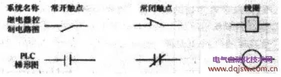
The component symbols in the relay control principle diagram include normally open contacts, normally closed contacts, and coils. To distinguish them, labels such as KM, KA, KT, etc., are marked next to the relevant symbols to indicate different devices, but the number of their contacts is limited. In the PLC ladder diagram, there are also normally open and normally closed contacts, which can similarly be marked with X, Y, M, S, T, C to indicate different soft devices. Its greatest advantage is that the same marked contact can reappear in different rungs. This is something that relays cannot achieve. The use of coils is the same; different coils can only appear once.
2. Classification of programming components:
Programming components are divided into eight categories: X for input relays, Y for output relays, M for auxiliary relays, S for status relays, T for timers, C for counters, and D for data registers and pointers (P, I, N). The functions of various components are introduced in various versions of PLC books, so they will not be introduced here, but it is essential to understand the functions of each type of component.
3. The instructions for programming components consist of two parts:
For example, LD (function meaning) X000 (component address), that is, LD X000, LDI Y000……
4. Familiarize yourself with basic PLC instructions:
(1) LD (take), LDI (take inverse), OUT (output) instructions; LD (take) and LDI (take inverse) are commonly referred to as normally open and normally closed in electrical terms. These two instructions are most often used as the first contact of each circuit (i.e., the first contact of the left bus), and of course, they may also appear in the first contact of a circuit block in parallel with others.This is a PLC ladder diagram (will not run). The vertical line on the left is called the left bus, and the right bus may not be represented. This diagram has three rungs; the first rung; the first contact on the left is normally open, marked as X000, where X represents the input relay, and the subsequent 000 data can be considered as using the contact numbered 000 in the input relay (the same applies below). The correct representation of its instruction should be (as shown in the right diagram): 0, LD X000 (the leading 0 indicates starting from step 0, the instruction input does not need to be considered, it will automatically display in order). The second rung; the first contact on the left is a normally closed contact, marked as T0, T represents the timer (with varying time lengths, attention is needed), and 0 indicates the contact numbered 0 in the timer. The correct representation of its instruction should be: 2, LDI T0 (as shown in the program). The third rung; the first contact on the left is normally closed, marked as M0, M is an auxiliary relay (this relay has various types, attention is needed), and the correct representation of its instruction should be: 4, LDI M0 (as shown in the program). The first contact of the second row of this rung is normally open, marked as Y000, Y represents the output relay, since this contact is in series with the subsequent Y001 contact, forming a so-called circuit “block”, thus its contact instruction should be 5, LD Y000. In summary, LD and LDI instructions can be seen to be used for the first contact of each rung on the left bus. The branches in the rung (i.e., the second line of the third rung) have two or more contacts in series, and their first contact also follows the LD or LDI instruction. The components that can use LD, LDI instructions include: input relay X, output relay Y, auxiliary relay M, timer T, counter C, and status relay S. OUT is a coil drive instruction, and this instruction cannot appear in the first position of the left bus. Drive coils cannot be connected in series but can be connected in parallel. The same drive coil can only appear once and should be arranged at the last position of each rung. For example, in the above diagram, 1, OUT Y000, 3, OUT Y001, Y is the output relay, and once the coil receives the output signal, it can be considered that the coil will drive its corresponding contact to connect the external load (external loads are mostly contactors, intermediate relays, etc.). In the above diagram, 8, OUT T0 K40 is the timer drive coil instruction, where K is a constant 40 is the set value (similar to the electrician’s adjustment of time relays). The components that can use the OUT instruction include: output relay Y, auxiliary relay M, timer T, counter C, and status relay S.
(2) Series contact instructions AND (and) ANI (nand); the former is normally open, and the latter is normally closed. Both are used for the series connection of single contacts. These two instructions can be repeated without limitation. As shown in the diagram.From the first rung; X000, T0, and Y001 three contacts are in series, that is, T0’s normally closed is connected to the back end of X000, while Y001’s normally closed is connected to the back end of T0’s normally closed. Since they are all normally closed, the ANI instruction is used. Now looking at the second rung; X000, M0, and Y001, similarly, the three contacts are also in series, M0’s normally closed contact is connected to the back end of X001, while Y000’s normally open contact is connected to the back end of M0. Therefore, M0’s instruction uses ANI, while Y000’s instruction uses AND (specific programming detailed in the diagram), as long as the series connection is normally open, use AND, if normally closed, use ANI. Components that can use AND, ANI instructions include: input relay X, output relay Y, auxiliary relay M, timer T, counter C, and status relay S. (3) Parallel contact instructions OR (or), ORI (nor); when contacts are connected in parallel, regardless of how many branches are in the rung, as long as a single contact is in parallel with the previous branch, if normally open, use OR, if normally closed, use ORI. As shown in the diagram.
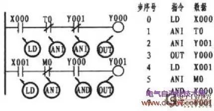 From the first rung; X000, T0, and Y001 three contacts are in series, that is, T0’s normally closed is connected to the back end of X000, while Y001’s normally closed is connected to the back end of T0’s normally closed. Since they are all normally closed, the ANI instruction is used. Now looking at the second rung; X000, M0, and Y001, similarly, the three contacts are also in series, M0’s normally closed contact is connected to the back end of X001, while Y000’s normally open contact is connected to the back end of M0. Therefore, M0’s instruction uses ANI, while Y000’s instruction uses AND (specific programming detailed in the diagram), as long as the series connection is normally open, use AND, if normally closed, use ANI. Components that can use AND, ANI instructions include: input relay X, output relay Y, auxiliary relay M, timer T, counter C, and status relay S.
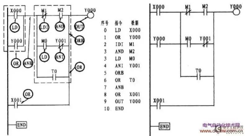
(3) Parallel circuit block with series instruction ANB; as shown in the lower left diagram, the two circuit blocks are connected in series, each circuit block is first connected in parallel and then connected in series with the ANB instruction. The ladder diagram on the left can be simplified using the diagram on the right. The program is written as shown in the diagram. The ANB instruction has no ladder diagram or data display. It can be considered as a horizontal line that connects the formed circuit block with the previous line in a vertical manner (as shown by the two thick lines in the diagram).
 (6) Stack instructions MPS, read stack instructions MRD, out stack instructions MPP, and program end instructions END; MPS, MRD, MPP is a group of stack instructions. As shown in the diagram, two types of stack forms are used; in the stack form, MPS should be used in pairs with MPP. For example, in the first stack form, MPS and MPP instructions are used. If there are branches appearing between the MPS and MPP instructions, then add the MRD instruction, as shown in the second stack of the diagram. It should be known that the number of times MPS and MPP should appear in pairs should be less than 11 times, while the MRD instruction can be used repeatedly but not exceeding 24 times. It should be known that this group of instructions also does not have a ladder diagram or data display. It can be considered that MPS is the starting point of the stack, serving as a connecting point, while the branch MRD and MPP are connected sequentially. The END instruction is the end instruction, which appears at the end of each program.
Of course, there are other instructions, but as long as you are familiar with and apply the above instructions, I believe that entering the door should not be a problem, and it is sufficient. Once you enter the door, studying other instructions will not be very difficult, so I will not explain them one by one.
4. Familiarize yourself with the functions of various keys on the simple programmer:
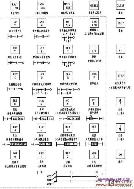
The following is the distribution of the FX-10P (handheld programmer) panel (of course, it lacks the liquid crystal display) and the functions of each key. The Chinese and component symbols marked below each key are all added by me (the purpose is to make it easier to find objects during input), and the rest are the same as the original keyboard (i.e., the English and numbers in the solid line box).
(1) LCD display; during programming, it can display instructions (i.e., instructions, component symbols, data). During monitoring and operation, it can display the working status of components.
(2) Keyboard; consists of 35 keys, including function keys, instruction keys, component symbol keys, and data keys, most of which can be switched. The functions of each key are as follows:
① Function keys: RD/WR…… read/write, if R appears in the lower left corner, it means program readout, if W appears, it means writing, that is, when inputting the program, W should appear; otherwise, the program cannot be input. Pressing the first time is R, and pressing again becomes W. INS/DEL…… insert/delete, if a program is missed during input, this key should be pressed, and I will appear to input the missing program. If it is found that an extra program is input, press this key again, and D will appear to delete the extra or erroneous program. MNT/TEST…… monitor/test, T is for testing, M is for monitoring, pressing this key can switch between them. When learning, you should learn to use the monitoring key M to monitor the running status of the program to help identify and solve problems.
② Menu key: OTHER, display mode menu.
③ Clear key: CLEAR, pressing this key can clear the currently input data.
④ Help key: HELP, displays a list of application instructions, during monitoring mode, conversion between decimal and hexadecimal numbers.
⑤ Step key: STEP, monitor the input step sequence number.
⑥ Space key: /SP, when inputting instructions, used to specify component numbers and constants.
⑦ Cursor keys: ↑, ↓, these two keys can move the cursor on the LCD display, scrolling up or down.
⑧ Execute key: GO, this key is used to confirm input instructions, execute insertions, deletions, etc.
⑨ Instruction key/component symbol key/numeric key (dashed box): These keys can automatically switch, the upper part is the instruction key, and the lower part is the component symbol key or numeric key. Once the instruction key is pressed, other keys switch to component symbols or numbers for selection input. Other Z/V, K/H, P/I can also switch among the same key.
5. Familiarize yourself with the operation of the programmer.
Connect the PLC and the simple programmer as specified. Power on the PLC, and the small indicator light will light up. Turn the knob switch on the PLC to the STOP position.
Key points of operation:
① Clear: Turn the knob switch to the STOP position, and English will appear, do not worry about it. Directly press RD/WD (so that the left side of the display shows W, which is the writing state), at this time, first press NOP, then press A in MC/A, and then press GO twice to confirm (i.e., W→NOP→A→GO→GO).
② Input instructions: For example, the instruction LD X000, input in the following order LD→X→0→GO, the screen will automatically display LD X000. Other instructions are similar. For instructions like ORB, ANB, MPS, MRD, MPP, END, NOP, etc., after inputting, just press GO to confirm (ORB→GO).
③ Timer input: For example, the instruction OUT T0 K 40, input in the following order OUT→T→0→/SP→K→40→GO (T0 is in units of 100ms, the set value is: 100×40=4000ms=4S).
④ Delete instructions: Move the cursor to the instruction you want to delete, set the INS/DEL key to D, and then confirm with GO. That is: move the cursor to the instruction you want to delete→D→GO.
⑤ Insert instructions: If you want to insert a new step between steps 4 and 5, move the cursor to 5, set the INS/DEL key to I, confirm, then input the new program and confirm again. For example, to insert AND Y001, that is: move the cursor to the desired insertion position→I→GO→AND→Y→1→GO.
⑥ GO key: After each step input is completed, you should press GO to confirm.
⑦ End instruction: At the end of each program input, the END instruction should be input, and the program can run.
⑧ After inputting the instructions, turn the knob switch on the PLC to RUN to enter the operating state. If there is sound or lights on, it indicates that there is a problem with the input program.
6. Input a simple runnable program and run it in monitoring mode:
When starting, you must learn to use the monitoring key M, which allows you to monitor the running status of the program from the LCD display, deepening your understanding of the operation of each PLC contact. This is the best way to identify and solve problems.
The specific operation is as follows: press the MNT/TEST key to set to M monitoring running mode, and move the cursor to observe the running status of the entire program. If the program shows a ■ mark, it indicates that the component is in the conductive state (ON), if there is no ■ mark, it indicates that the component is in the disconnected state (OFF).
7. Try to draw a simple ladder diagram:
The drawing of a simple ladder diagram generally starts with existing electrical principle diagrams, drawing according to their working principles, from shallow to deep, first aiming to draw it, then aiming for simplicity and clarity, gradually understanding the insights of drawing ladder diagrams. First, you need to understand the working principle of the electrical principle diagram, and then draw according to the requirements of the PLC. What is crucial is that you cannot simply correspond each PLC contact with each contact on the electrical principle diagram (this is a common problem among beginners); if you do this, you may fall into a dead end, and the drawn ladder diagram should achieve the purpose.
① Non-reversible start changed to PLC control
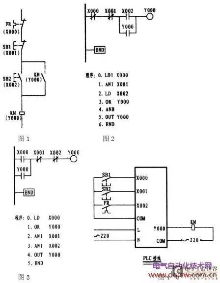
In the above diagram, Figure 1 is the electrical principle diagram, and Figure 2 is the ladder diagram drawn according to the principle diagram correspondence, which is easy to understand. However, in my impression, there are not many that can be drawn like this. If you use this method to draw, you may fall into an irreversible path. Although both diagrams can run, if Figure 2 is changed to become Figure 3, it can be seen that Figure 3 is missing a step ANB in the program. Simplicity and clarity are essential elements of programming. Therefore, when drawing the ladder diagram, try to place multiple parallel contacts on the side of the ladder diagram’s bus to reduce the ANB instruction. The X000 in Figure 2 and the X002 in Figure 3 are normally closed contacts controlled by the external thermal relay, while the thermal relay can also be connected in series with the contactor coil using normally open contacts. Only after drawing the ladder diagram can the program be compiled according to the ladder diagram.
Working principle: Taking Figure 3 as an example, when the external start button is pressed, the normally open contact X000 immediately closes the current (actually the energy flow), flowing through the normally closed contacts X001 and X002 to cause the output relay Y000 to close. Since Y000 closes, the normally open contact Y000 connected to the bus side closes, forming a self-holding relationship, which activates the external contactor, thus controlling the operation of the motor. When stopping, pressing the external stop button causes the normally closed contact X001 to momentarily disconnect the flow, thus cutting off the output relay coil, and the external contactor stops operating. When the motor is overloaded, the normally closed contact of the external thermal relay closes, causing the normally closed contact X002 to open, thus protecting the motor.
② Starting and jogging control changed to PLC control
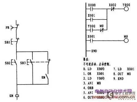
This question is often a hurdle that beginners cannot overcome. This is mainly caused by the composite button used in the relay electrical principle diagram, forming a fixed thinking pattern. From the ladder diagram, it can be seen that X001 is the momentary control contact. Since the left electrical principle diagram uses a composite button, the thinking naturally turns to using the normally closed contact of X001 to form a similar effect with the normally open contact of X001, which is a good imagination. It should be known that PLC operates in a scanning manner, processing each statement in order at a very fast speed. If the normally closed contact of X001 is used to replace the normally closed contact of M0, when the external momentary button is pressed, the normally open contact X001 will close while the normally closed contact will open. However, once released, its normally closed contact will almost immediately close, forming a self-holding state, thus losing the momentary function. The second branch of the first rung in the ladder diagram is connected in series with the normally closed contact of the output relay Y000 and the normally closed contact of the intermediate relay M0. In such a case, if allowed, it should be placed in the first row, so that the programming can use fewer ORB instructions.
Working principle: This ladder diagram does not set thermal relay contacts; it only sets a stop contact. Pressing the external start button causes the normally open contact X000 to close, and the current (energy flow) flows from the bus through X002 to connect the output relay Y000, which closes. Due to the closure of Y000, the normally open contact Y000 connected to the bus side closes, forming a self-holding relationship, thus driving the external contactor to activate the motor. When stopping, pressing the external stop button causes the normally closed contact X002 to momentarily disconnect, resulting in the output relay losing power, and the motor stops rotating. When the motor is overloaded, the normally closed contact of the external thermal relay closes, leading to the normally closed contact X002 opening, thus protecting the motor.
③ Contactor interlocking forward and reverse control changed to PLC control
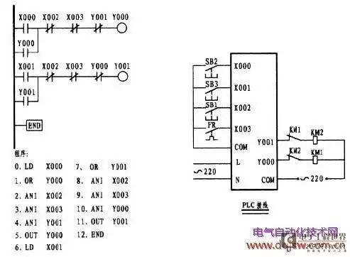
In this diagram, the first rung and the second rung on the bus side include normally open contacts X000 and X001 controlled by external buttons SB2 and SB3. Once an external signal is received, the corresponding X000 or X001 closes, allowing the respective output relay Y000 or Y001 coil to close through the series connection of the corresponding lines in the first or second rung. The closure of the output relay coil causes one of the normally open contacts Y000 or Y001 in the first and second rungs to close, forming a self-holding relationship. The external contactor connected to the output relay then drives the motor to run. Stopping is controlled by the external button SB1, which causes the normally closed contact X002 connected in series with the first and second rungs to disconnect, cutting off power regardless of forward or reverse, thus stopping the motor. Thermal protection is driven by the external FR, causing the normally closed contact X003 connected in series with the first and second rungs to disconnect, stopping the motor. The normally closed contacts Y001 and Y000 connected in series with the first and second rungs serve to ensure that when running in the forward direction, the reverse circuit is cut off, and similarly, when running in the reverse direction, the forward circuit is cut off, allowing them to operate in only one state, essentially interlocking each other. It should be particularly emphasized that due to the extremely fast speed of PLC operation, if there is no necessary external interlocking in the forward and reverse control state, it will cause a short circuit. Relying solely on internal interlocking of the PLC is not sufficient. This point must be remembered by beginners. Moreover, this issue should be considered in necessary circuits such as star-delta reduction starting.
④ Composite interlocking forward and reverse energy consumption braking using PLC modification
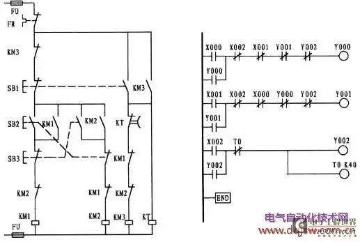
Program: 0, LD X000 1, OR Y000 2, ANI X002 3, ANI X001 4, ANI Y001 5, ANI Y002 6, OUT Y000 7, LD X001 8, OR Y001 9, ANI X002 10, ANI X000 11, ANI Y000 12, ANI Y002 13, OUT Y001 14, LD X002 15, OR Y002 16, ANI T0 17, OUT Y002 18, OUT T0 K 40 21, END
This diagram illustrates the energy consumption braking control modified to use PLC. Its working principle is as follows: When the external forward button SB1 is pressed, it drives the normally open contact X000 of the first rung to close (while the normally closed contact X000 of the second rung simultaneously opens, cutting off the possible running of the reverse function, providing interlocking). The series connection of the following contacts X002, X001, Y001, and Y002 all normally closed allows the output relay coil Y000 to close. Due to the closure of the Y000 coil, the normally open contact Y000 connected to the bus side closes, forming a self-holding relationship (while the normally closed contact of Y000 in the second rung opens, ensuring that reverse is not allowed during forward operation, providing interlocking). The closure of Y000 activates the forward contactor, driving the motor to work. The working of the second rung is similar to that of the first rung: pressing the external reverse button SB2 drives the normally open contact X001 of the second rung to close (while the normally closed contact X001 of the first rung simultaneously opens, cutting off the possible running of the forward function, providing interlocking). The series connection of the following contacts X002, X000, Y000, and Y002 all normally closed allows the output relay coil Y001 to close. Due to the closure of the Y001 coil, the normally open contact Y001 connected to the bus side closes, forming a self-holding relationship (while the normally closed contact of Y001 in the first rung opens, ensuring that forward is not allowed during reverse operation, providing interlocking). The closure of Y001 activates the reverse contactor, driving the motor to work. To stop, press the external button SB3, which drives the normally closed contact X002 connected to the first, second, and third rungs to open, cutting off the running of the motor. The timer T0 is also connected in series with the output relay Y002, allowing the output relay coil Y002 and timer coil T0 to close. The closure of Y002 activates the external contactor KM3, which provides direct current to the motor for energy consumption braking. The aforementioned timer and Y002 close simultaneously, and the timer starts counting. The timing time is 4 seconds (calculation method: the unit time of T0 is 100ms, and K is set to 40, so 100×40=4000ms; 1S=1000ms). Once the 4 seconds is up, the normally closed contact T0 in the third rung opens, stopping the operation. This ladder diagram does not set thermal relay contacts; you can set normally closed contacts X003 in front of the coils of Y000 and Y001 in the first and second rungs, respectively. Similarly, since this circuit is a forward-reverse circuit, necessary contactor auxiliary contact interlocking should be considered externally.
⑤ Power-off delay star-delta reduction starting energy consumption braking control modified to PLC control
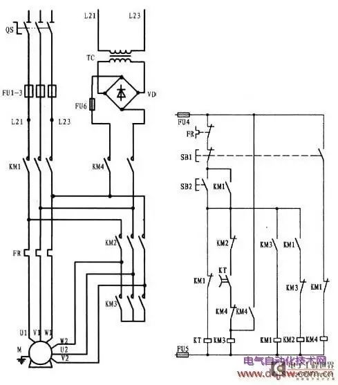
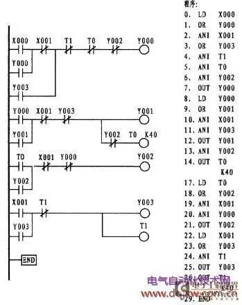
The PLC does not have a power-off delay timer; it only has a power-on delay timer. The working principle of this ladder diagram is as follows: When the external start button SB2 is pressed, it drives the normally open contact X000 of the first rung to close, allowing current to flow through the series connection of the normally closed contacts X001, T1, T0, and Y002 to activate the output relay. Due to the closure of the Y000 coil, it causes the normally open contact Y000 in the first rung to close, forming a self-holding relationship, thus activating the external contactor KM3, connecting the motor windings in a star configuration. Meanwhile, the normally open contact Y000 in the second rung closes, allowing current to flow through the series connection of the normally closed contacts X001 and Y003 to activate the output relay Y001 and another branch through the normally closed contact Y002 connected in series with the timer coil T0 (K value is 40). Due to the closure of the Y001 coil, the normally open contact Y001 connected to the bus side closes, forming a self-holding relationship. The closure of Y001 activates the external contactor KM1, putting the motor in a star connection for starting. When Y001 closes, timer T0 also begins counting. After 4 seconds, the normally closed contact T0 in the second rung opens, disconnecting the output relay Y000 coil, releasing the star connection. At the same time, the normally open contact T0 in the third rung closes, allowing the output relay Y002 to activate. The closure of Y002 activates the external contactor KM2, completing the star-delta conversion and switching the motor to a delta connection. When stopping, pressing the external stop button SB1 will disconnect the normally closed contacts X001 in the first, second, and third rungs, allowing the motor to stop in any running state. The fourth rung X001 connects to the normally open contact; once it closes, it allows the series connection of the normally closed contacts to activate the output relay Y003 and timer T1. The closure of Y003 activates the normally open contact Y003 in the second rung, driving KM3 to provide direct current to the motor for energy consumption braking. The timer coil T1 is powered simultaneously with the closure of Y003 and begins counting. Once the timer time is up, the normally closed contact in the first rung and the normally closed contact in the fourth rung open, completing the stopping and braking process of the motor. When wiring external contactors, interlocking between contactors should be considered to prevent short circuits. Additionally, this ladder diagram does not set thermal protection.
⑥ Dual-speed asynchronous motor control circuit modified to PLC control
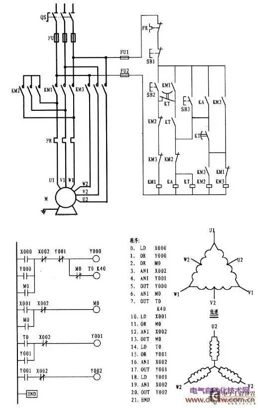
This circuit controls a dual-speed motor, which is generally not well understood by most people. The motor model is YD123M-4/2, 6.5/8KW, Δ/Y. According to the model interpretation, this motor has two speeds: 4 poles and 2 poles. At 4-speed, the motor power is 6.5KW, and the winding is connected in a delta configuration. If at 2-speed, the motor power is 8KW, and the winding is connected in a double star configuration. This motor has a total of 6 connection heads; during delta connection (low speed), power is connected via U1, V1, W1, while the remaining heads U2, V2, W2 are left floating. During star connection (high speed), the heads U1, V1, W1 are connected to form a star point, and the three-phase power is input via U2, V2, W2 (the motor connection diagram is shown above). The requirement for this circuit is that the motor can run at either low speed or high speed but must start at low speed before switching to high speed. You can analyze based on the electrical principle diagram.
The working principle of the ladder diagram: pressing the external start button SB3 connects the normally open contact X000 on the bus side of the first rung, allowing current (energy flow) to pass through the series connection of the normally closed contacts X002 and Y001 to activate the output relay coil Y000. Due to the closure of Y000, the normally open contact Y000 connected to the bus side closes, forming a self-holding relationship. The closure of Y000 activates the external contactor KM1, putting the motor in low-speed starting mode (i.e., in delta connection). At the same time, the timer T0 in the second rung, connected in series with the normally closed contact X000, starts counting. Once the timer time is up, the normally open contact T0 in the third rung closes, allowing the series connection of the normally closed contact X002 to activate the output relay Y001. The closure of Y001 activates the normally open contact Y001 connected to the bus side, forming a self-holding relationship. The closure of Y001 activates the external contactor KM2, connecting the motor windings’ heads U1, V1, W1 to form a star point, allowing the motor to run at high speed. To stop, press the external button SB1. The normally closed contacts connected in series in each rung will open, allowing the motor to stop in any running state. This is the process of low-speed starting and high-speed running.
This ladder diagram does not set thermal protection; based on the original diagram, thermal protection is missed. You can connect normally closed contacts X003 in the first rung after the coils of Y001 and Y002, respectively.
⑦ Use PLC to design a ladder diagram
Requirements: There are three motors, labeled as Motor 1, Motor 2, and Motor 3. After Motor 1 starts, Motor 2 will automatically start after 4 seconds, and Motor 3 will automatically start 4 seconds after Motor 2 starts.
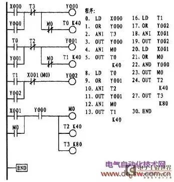
The idea is as follows: Based on the requirements, set two input signal buttons, SB1 and SB2. SB1 serves as the stop button to control the normally open contact X001 on the bus side of the fourth rung in the ladder diagram. SB2 serves as the start button to control the normally open contact X000 on the bus side of the first rung in the ladder diagram. Since there are three motors, set three output relays: Y000, Y001, and Y002, with Y000 connected to contactor KM1, Y001 connected to contactor KM2, and Y002 connected to contactor KM3, each controlling Motor 1, Motor 2, and Motor 3, respectively. When starting, Motor 1 is controlled by the button, while Motors 2 and 3 start based on a timed principle, thus two timers, T0 and T1, should be set. When stopping, Motor 3 can be controlled using the button, while Motors 2 and 1 also stop based on a timed principle, thus two timers, T2 and T3, should be set. After determining these devices, sketch them out with a pencil on paper, and then arrange these soft devices reasonably, optimizing as necessary.
Working principle: Pressing the external button SB2 drives the normally open contact X000 on the bus side of the first rung, allowing current to flow through the normally closed contact of the timer T3 to activate the output relay Y000 coil and the timer coil T0 connected in series with the normally closed contact M0. Due to the closure of Y000, the normally open contact Y000 connected to the bus side closes, forming a self-holding relationship (at the same time, the normally open contact Y000 in the fourth rung closes, preparing for stopping). Motor 1 starts. The timer connected in series with Y000 also starts counting. Once the timer time is up, the normally open contact T0 in the second rung closes, allowing current to flow through the series connection of the normally closed contact T2 to activate the output relay Y001 coil and the timer coil T1 connected in series with the normally closed contact M0. The normally open contact Y001 connected to the bus side closes, forming a self-holding relationship, and Motor 2 starts. Once Y001 closes, the timer connected in series starts counting. When the timer time is up, the normally open contact T1 in the third rung closes, allowing current to flow through the series connection of the normally closed contact X001 to activate the output relay Y002 coil. Due to the closure of Y002, the normally open contact Y002 connected to the bus side closes, forming a self-holding relationship, and Motor 3 starts. To stop, press the external button SB1, which drives the normally closed contact X004 to open, stopping Motor 3. At the same time, the normally open contact X001 in the fourth rung closes. Current flows through the series connection of the normally open contact (at this time, due to the closure of Y000, it has become closed) to activate the intermediate relay M0. The closure of M0 activates the normally open contact M0 connected to the bus side, forming a self-holding relationship. The closure of M0 simultaneously activates the timers T2 and T3. They start counting, and since T2’s counting time is 4 seconds, once the time is up, the normally closed contact T2 in the second rung opens, stopping Motor 2. After another 4 seconds, the normally closed contact T3 in the first rung opens, stopping Motor 1. Once Y000 loses power, the normally open contact Y000 in the fourth rung opens, and the ladder diagram stops running. The role of the normally closed contact M0 in front of timers T0 and T1 in the first and second rungs is to prevent the motor from restarting after stopping.
⑧ Use PLC to design a ladder diagram
Requirements: There are two motors, labeled as Motor 1 and Motor 2. Motor 1 can rotate in both directions, while Motor 2 only rotates in one direction. Motor 2 can only start when Motor 1 is rotating forward. Once Motor 1 starts, it cannot stop, but it can switch between forward and reverse. To stop, Motor 2 must stop while Motor 1 is reversing; only after that can Motor 1 stop.
 The idea is as follows: Since there are two motors, Motor 1 requires forward and reverse rotation, with external forward and reverse start buttons SB1 (controlling X000) and SB2 (controlling X001), and a stop button SB3 (controlling X004). Set one output relay Y000 and Y001, each controlling the contactor KM1 and KM2 for forward and reverse. Set one external start button SB4 (controlling X002) for Motor 2 and a stop button SB5 (controlling X003). A total of 5 input relays and 3 output relays are required. Sketch them out on paper, and arrange these soft devices reasonably in series and parallel; if necessary, add intermediate relays for optimization.
Working principle: Pressing the external button SB1 connects the normally open contact X000 on the bus side of the first rung, allowing current to flow through the normally closed contacts X001 and Y001 to activate the output relay Y000 coil. Due to the closure of Y000, the normally open contact Y000 connected to the bus side closes, forming a self-holding relationship, allowing the output relay Y000 to output a signal, controlling the external contactor KM1 to drive forward operation. When X000 closes, the normally closed contact of X001 in the second rung opens, cutting off the possible reverse operation, providing interlocking. At the same time, due to the closure of Y000, the normally closed contact of Y000 in the second rung opens, which is similar to the interlocking of the auxiliary contacts of the forward and reverse contactors. The normally open contact Y002 in the third rung prepares for Motor 2’s start. Pressing the external button SB1 connects the normally open contact X001 on the bus side of the second rung, allowing current to flow through the normally closed contacts X004, Y000, and Y001 to activate the output relay Y001 coil. Due to the closure of Y001, the normally open contact Y001 connected to the bus side closes, forming a self-holding relationship, allowing the output relay Y001 to output a signal, controlling the external contactor KM2 to drive reverse operation. When X001 closes, the normally closed contact of X001 in the first rung opens, cutting off the possible forward operation, providing interlocking. At the same time, due to the closure of Y001, the normally closed contact of Y001 in the first rung opens, which also provides an interlocking relationship. Similarly, when X001 closes, the normally open contact Y002 in the fourth rung closes, allowing current to flow through the normally closed contact of the intermediate relay M0, activating the M0 coil, which forms a self-holding relationship through the normally open contact M0 on the bus side. The normally closed contact of M0 connected to the lower end of X004 in the second rung closes, thus limiting the stopping of Motor 1 while in a forward or reverse state (since the line requires that the motor cannot stop when in forward or reverse). The normally open contact Y002 connected in parallel with the normally closed contact of X004 serves to limit the advance stop of Y001 compared to Y002.
Pressing the external button SB4 connects the normally open contact X002 on the bus side of the third rung, allowing current to flow through the normally open contact Y000 (which only allows when Y000 is closed, meaning Motor 1 is in the forward state) and the normally closed contact X003, activating the output relay Y002 coil. Due to the closure of Y002, the normally open contact Y002 connected to the bus side closes, forming a self-holding relationship. The closure of Y002 activates the external contactor KM3, driving Motor 2 to run. When Y002 closes, the normally open contact Y002 in the second rung closes, thus limiting the possibility of Motor 1 stopping before Motor 2 during the reverse state. At this point, pressing the external button SB5 will cause X003 to open, disconnecting the output relay Y002 coil and stopping Motor 2. Due to the disconnection of Y002, the normally open contact Y002 connected to the lower end of X004 opens (thus restoring the original state), preparing for the stopping of Motor 1. Only by pressing the external button SB3 can the normally closed contact X004 be disconnected, thus disconnecting Y001 and ending the ladder’s running program.
Guidance Car Robot Academy – PLC Application Course!
|
PLC Application Course |
||||
|
Course Content |
Course Objectives |
Duration |
Location |
Start Date |
|
PLC fundamentals and instruction system; PLC program architecture and development process; bus systems and applications; system project training |
1. Master the application examples of FX3U in the industrial control industry. 2. Familiarize with the corresponding instructions, modules, and operations of FX3U. 3. Use FX3U for development and program optimization. |
5 days (40h) |
Hangzhou |
September 12 – September 16 |
Classic Review
Analysis of seven-axis flexible multi-joint robots, worth savoring!
How to become an industrial robot application engineer?
Boosting “China Intelligent Manufacturing”, our common mission

 Guidance Car Robot Academy | Robotics Craftsman Workshop