1. Overview
For many years, the Programmable Logic Controller (PLC) has made a leap from wiring logic to storage logic since its inception; its functions have progressed from weak to strong, achieving advancements from logic control to digital control; its application fields have expanded from simple control of individual devices to various tasks such as motion control, process control, and distributed control. Today’s PLCs have significantly improved their capabilities in handling analog quantities, digital operations, human-machine interfaces, and networking, becoming mainstream control devices in the field of industrial control and playing an increasingly important role across various industries.
2. Application Fields of PLC
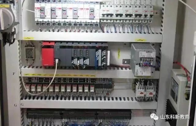
Currently, PLCs are widely used in various industries including steel, petroleum, chemical, electric power, building materials, machinery manufacturing, automotive, light textiles, transportation, environmental protection, and cultural entertainment, with usage primarily categorized as follows:
1. Switch Quantity Logic Control
Replacing traditional relay circuits, PLCs achieve logic control and sequential control, suitable for both single device control and multi-machine group control as well as automated assembly lines. Examples include injection molding machines, printing machines, stapling machines, CNC machines, grinding machines, packaging production lines, and electroplating lines.
2. Industrial Process Control
In industrial production processes, there are continuous variables such as temperature, pressure, flow, liquid level, and speed (i.e., analog quantities). PLCs use corresponding A/D and D/A conversion modules and various control algorithm programs to handle analog quantities and complete closed-loop control. PID regulation is a commonly used method in general closed-loop control systems. Process control is widely applied in metallurgy, chemical engineering, heat treatment, boiler control, and other scenarios.
3. Motion Control
PLCs can be used to control circular or linear motion. Specialized motion control modules are generally used, such as single-axis or multi-axis position control modules that can drive stepper motors or servo motors, widely applied in various machinery, machine tools, robots, elevators, etc.

4. Data Processing
PLCs have capabilities for mathematical operations (including matrix operations, function operations, logical operations), data transmission, data conversion, sorting, lookup tables, bit operations, etc., enabling data collection, analysis, and processing. Data processing is generally used in large control systems in industries such as papermaking, metallurgy, and food processing.
5. Communication and Networking
PLC communication includes communication between PLCs and between PLCs and other intelligent devices. With the development of factory automation networks, modern PLCs come with communication interfaces, making communication very convenient.
3. Characteristics of PLC Applications
1. High Reliability and Strong Anti-Interference Ability
High reliability is a key performance indicator for electrical control devices. PLCs, due to their use of modern large-scale integrated circuit technology and strict manufacturing processes, incorporate advanced anti-interference technologies in their internal circuits, resulting in very high reliability. Compared to equivalent relay contactor systems, the electrical wiring and switching contacts in control systems using PLCs have been reduced to hundreds or even thousands of times less, significantly lowering the likelihood of faults. Additionally, PLCs come equipped with hardware fault self-detection functions that can promptly issue alarm information in case of faults. In application software, users can also program self-diagnosis routines for peripheral devices, providing fault self-diagnosis protection for circuits and equipment outside the PLC. This ensures extremely high reliability for the entire system.
2. Comprehensive Support, Complete Functions, Strong Applicability
PLCs have developed into a series of products of various scales, suitable for various sizes of industrial control scenarios. In addition to logic processing capabilities, most PLCs possess comprehensive data processing capabilities, making them suitable for various digital control fields. A wide variety of functional units have emerged, allowing PLCs to penetrate various industrial control applications such as position control, temperature control, CNC, etc. Coupled with enhanced PLC communication capabilities and the development of human-machine interface technology, it has become very easy to construct various control systems using PLCs.
3. Easy to Learn and Use, Highly Popular Among Engineering Technicians
PLCs are industrial control devices aimed at mining and manufacturing enterprises. They feature easy interfaces and programming languages that are readily accepted by engineering technicians. The graphical symbols and expression methods of ladder diagram language are quite similar to relay circuit diagrams, making it easier for individuals unfamiliar with electronic circuits or computer principles to engage in industrial control.
4. Reduced Workload in System Design, Easy Maintenance, and Modifications
PLCs replace wiring logic with storage logic, significantly reducing the external wiring of control devices, which shortens the design and construction cycle of control systems, while also making daily maintenance easier. More importantly, it allows the same device to change production processes by altering programs, which is particularly suited for production environments with multiple varieties and small batches.
4. Issues to Note in PLC Applications
PLCs are devices used for automated control in industrial production and generally do not require special measures for direct use in industrial environments. However, despite their high reliability and strong anti-interference capabilities, if the production environment is excessively harsh, with particularly strong electromagnetic interference or improper installation and use, it may lead to program errors or calculation errors, resulting in incorrect inputs and outputs, causing loss of control and erroneous actions, which can compromise the normal operation of the PLC. To enhance the reliability of PLC control systems, it is necessary for PLC manufacturers to improve the anti-interference capabilities of their devices, and for design, installation, and maintenance to be given high priority, requiring cooperation from multiple parties to effectively resolve issues and enhance the system’s anti-interference performance. Therefore, the following issues should be noted during use:
1. Working Environment
(1) Temperature
PLCs require an ambient temperature of 0~55°C and should not be placed under components that generate a lot of heat; there should be sufficient space around for ventilation and heat dissipation.
(2) Humidity
To ensure the insulation performance of the PLC, the relative humidity of the air should be less than 85% (no condensation).
(3) Vibration
PLCs should be kept away from strong vibration sources to prevent frequent or continuous vibrations with frequencies between 10~55Hz. If unavoidable, damping measures such as using damping rubber should be taken.
(4) Air Quality
Avoid corrosive and flammable gases, such as hydrogen chloride and hydrogen sulfide. For environments with high dust or corrosive gases, PLCs should be installed in well-sealed control rooms or cabinets.
(5) Power Supply
PLCs have a certain level of resistance to interference from power lines. In environments with high reliability requirements or severe power supply interference, an isolation transformer with a shielding layer can be installed to reduce interference between the equipment and ground. Generally, PLCs have a 24V DC output to provide power to input terminals. When using an external DC power supply for the input terminals, a DC regulated power supply should be selected. Ordinary rectifier-filter power supplies, due to ripple effects, can easily cause PLCs to receive incorrect information.
2. Interference and Its Sources in Control Systems
Electromagnetic interference in the field is one of the most common and easily impactful factors on the reliability of PLC control systems. To address the issue effectively, it is essential to identify the source of interference.

(1) Sources of Interference and General Classifications
The sources of interference affecting PLC control systems mostly arise from locations where current or voltage changes dramatically, as the change in current generates magnetic fields that induce electromagnetic radiation on the equipment; changes in magnetic fields generate currents that produce electromagnetic waves. Generally, electromagnetic interference is classified into common-mode interference and differential-mode interference based on the interference patterns. Common-mode interference refers to the potential difference of the signal to ground, primarily formed by common-mode voltage superimposed on the signal line due to the introduction of the power grid, ground potential differences, and spatial electromagnetic radiation. Common-mode voltage can be converted into differential-mode voltage through asymmetric circuits, directly affecting measurement and control signals, causing damage to components (this is a major reason for high failure rates in some system I/O modules). This common-mode interference can be either DC or AC. Differential-mode interference refers to the interference voltage acting between the two poles of the signal, mainly formed by coupling induction of spatial electromagnetic fields on the signal and by unbalanced circuits converting common-mode interference into voltage. This interference superimposed on the signal directly impacts measurement and control accuracy.
(2) Main Sources and Paths of Interference in PLC Systems
Strong Electrical Interference
The normal power supply for PLC systems is provided by the power grid. Due to the wide coverage of the power grid, it is susceptible to all spatial electromagnetic interference, which induces voltages on the lines. Particularly, internal changes in the power grid, such as switching operations, large electrical equipment starting and stopping, harmonics generated by AC and DC drive devices, and transient impacts from power grid short circuits, are transmitted to the power source through transmission lines.
Cabinet Interference
High-voltage electrical appliances and large inductive loads within control cabinets, along with messy wiring, can cause varying degrees of interference to PLCs.
Interference from Signal Lines
Various signal transmission lines connected to the PLC control system not only transmit effective information but also inevitably allow external interference signals to intrude. This interference mainly occurs through two pathways: first, through the power supply of transmitters or shared signal instruments, which can introduce power grid interference; second, through external induced interference on signal lines due to spatial electromagnetic radiation, which is quite serious. Interference introduced by signals can cause abnormal I/O signal operations and significantly reduce measurement accuracy, potentially leading to component damage in severe cases.
Interference from Confused Grounding Systems
Grounding is one of the effective means to enhance the electromagnetic compatibility (EMC) of electronic equipment. Proper grounding can suppress the influence of electromagnetic interference and prevent equipment from emitting interference; improper grounding can introduce severe interference signals, rendering the PLC system unable to function normally.
Internal Interference from PLC Systems
This mainly arises from mutual electromagnetic radiation between internal components and circuits, such as mutual radiation among logic circuits and their effects on analog circuits, the interaction between analog ground and logic ground, and the mismatched use of components.
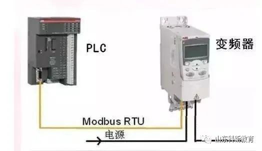
Inverter Interference
Firstly, the harmonics generated during the starting and operation of inverters can produce conducted interference on the power grid, causing voltage distortion and affecting the power supply quality; secondly, the output from inverters can generate strong electromagnetic radiation interference, affecting the normal operation of surrounding equipment.
3. Main Anti-Interference Measures
(1) Proper Handling of Power Supply to Suppress Interference from the Power Grid
To address power grid interference introduced through the power supply, an isolation transformer with a shielding layer and a 1:1 transformation ratio can be installed to reduce interference between the equipment and ground. Additionally, an LC filter circuit can be connected in series at the power input terminal. As shown in Figure 1.
(2) Installation and Wiring
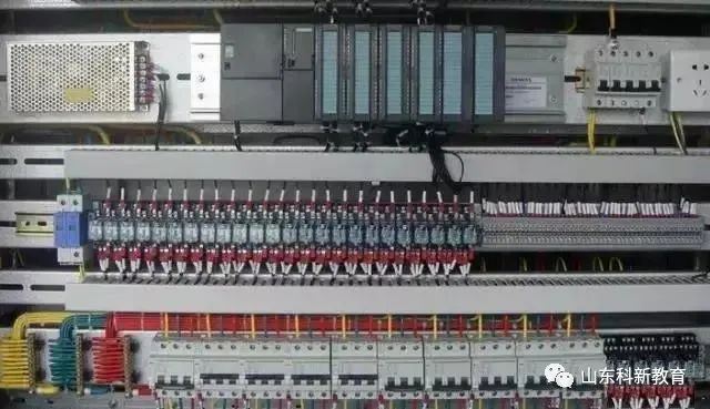
● Power lines, control lines, as well as the power supply and I/O lines of the PLC should be wired separately. Isolation transformers should be connected to the PLC and I/O using double-insulated wires. The PLC’s I/O lines should be routed separately from high-power lines; if they must share the same cable duct, AC and DC lines should be bundled separately. If conditions allow, it is best to route them in separate ducts to maximize spacing and minimize interference.
● PLCs should be kept away from strong interference sources such as welding machines, high-power silicon rectifiers, and large power equipment, and should not be installed in the same switch cabinet as high-voltage electrical appliances. Inside the cabinet, PLCs should be distanced from power lines (the distance should be greater than 200mm). Inductive loads, such as large relays and contactor coils, installed in the same cabinet as the PLC, should have RC snubber circuits connected in parallel.
● It is best to route the input and output lines of the PLC separately, and also separate digital signals from analog signals. For transmitting analog signals, shielded cables should be used, with the shielding layer grounded at one or both ends, and the grounding resistance should be less than one-tenth of the shielding layer resistance.
● AC output lines and DC output lines should not use the same cable; output lines should be kept as far away from high-voltage lines and power lines as possible to avoid parallel routing.
(3) Wiring of I/O Terminals
Input Wiring
● Input wiring should generally not be too long. However, if the environmental interference is minimal and the voltage drop is small, the input wiring can be slightly longer.
● Input and output lines should not use the same cable and should be separated.
● It is advisable to use normally open contact forms connected to the input terminals, making the compiled ladder diagrams consistent with relay principle diagrams for easier reading.
Output Connections
● Output terminal wiring can be categorized into independent output and common output. Different types and voltage levels of output voltages can be used in different groups, but outputs within the same group must use the same type and voltage level of power supply.
● Since the output components of the PLC are encapsulated on a printed circuit board and connected to terminal blocks, short-circuiting the load connected to the output components can destroy the printed circuit board.
● The size of inductive loads on relay outputs can affect the lifespan of the relay; therefore, inductive loads should be chosen wisely or isolation relays should be added.
● Output loads from PLCs can generate interference; therefore, measures should be taken to control it, such as using flyback diodes for DC outputs, RC snubber circuits for AC outputs, and bypass resistors for transistor and thyristor outputs.
(4) Correctly Selecting Ground Points and Improving the Grounding System
Good grounding is a crucial condition for ensuring the reliable operation of PLCs, as it can prevent accidental voltage spikes. The purpose of grounding generally includes safety and interference suppression. A well-structured grounding system is one of the important measures for enhancing the PLC control system’s resistance to electromagnetic interference.
The grounding system of the PLC control system includes system ground, shield ground, AC ground, and protective ground. A chaotic grounding system can interfere with the PLC system, primarily due to uneven potential distribution among various grounding points, leading to ground loop currents that affect normal system operation. For example, the cable shielding layer must be grounded at one point; if both ends A and B of the cable shielding layer are grounded, there will be a potential difference, resulting in current flowing through the shielding layer. In the event of an abnormal state such as lightning strikes, the ground current will increase.
Furthermore, the shielding layer, grounding wire, and ground may form a closed loop, generating induced currents under changing magnetic fields, which can interfere with signal circuits through coupling between the shielding layer and the core wire. If the system ground is confused with other grounding treatments, the ground loop currents generated may create uneven potential distributions on the ground wire, affecting the normal operation of the PLC’s logic and analog circuits. The interference tolerance of logical voltage in PLCs is low, and disturbances in the distribution of logic ground potential can easily impact the logical operations and data storage of the PLC, causing data confusion, program glitches, or system crashes. The distribution of analog ground potential can lead to decreased measurement accuracy, causing severe distortion and erroneous actions in signal measurement and control.
● Safety Ground or Power Supply Ground
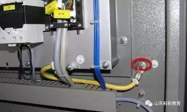
The grounding terminal of the power supply line and the cabinet grounding should be connected for safety grounding. If there is a power leakage or the cabinet is energized, the current will be directed into the ground safely, preventing harm to individuals.
● System Grounding
The PLC controller is grounded to ensure it is at the same potential as the devices it controls, known as system grounding. The grounding resistance should not exceed 4Ω, and generally, the PLC equipment’s system ground should be connected to the negative terminal of the power supply within the control cabinet, serving as the control system ground.
● Signal and Shield Grounding
Signal lines should have a unique reference ground. In environments where shielding cables may produce conducted interference, they should also be grounded uniquely at the local site or control room to prevent the formation of “ground loops.” When grounding signal sources, the shielding layer should be grounded on the signal side; if not grounded, it should be grounded on the PLC side. If there are junctions in the signal line, the shielding layer should be securely connected and insulated, avoiding multi-point grounding. When connecting shielded twisted pairs and multi-core twisted shielded cables, the shielding layers should be interconnected and properly insulated, selecting appropriate single-point grounding locations.
(5) Suppressing Interference from Inverters
There are several methods for handling interference from inverters:
Installing isolation transformers, mainly to address conducted interference from the power supply, can block most of the conducted interference before it reaches the isolation transformer.
Using filters, which have strong anti-interference capabilities, can prevent the interference generated by the equipment itself from being conducted to the power supply, and some filters may also have surge voltage absorption functions.
Using output reactors, adding AC reactors between the inverter and motor mainly reduces the electromagnetic radiation generated during energy transmission, which can affect the normal operation of other devices.
The interference within the PLC control system is a complex issue; therefore, comprehensive considerations of various factors should be made in anti-interference design to effectively suppress interference and ensure the normal operation of the PLC control system. As the application fields of PLCs continue to expand, how to use PLCs efficiently and reliably has become an important factor in their development.
5. Conclusion
In the future, PLCs will see greater development, with a richer variety of products and more complete specifications. Through improved human-machine interfaces and comprehensive communication equipment, they will better meet the demands of various industrial control scenarios. As an essential part of automation control networks and internationally standardized networks, PLCs will play an increasingly significant role in the field of industrial control.
Source: This article is reprinted from the internet, and the copyright belongs to the original author. If there are any copyright issues, please contact us promptly for deletion. Thank you!

Scan to Follow
WeChat ID|13615417996
Scan the QR code on the left to get 【Siemens Data Collection】 for free.