In intermittent production scenarios (such as material dryers and timed conveyor lines), it is often necessary for motors to operate in a cycle of “run for 2 hours, stop for 2 hours.” Today, we will use the Siemens S7-200 SMART PLC to guide you step by step from hardware wiring to program writing to achieve this function, making it easy for beginners to follow along.
1. Clarify the control logic: Avoid unnecessary detours in the program
Core requirement: After pressing the “Start” button, the motor automatically runs for 2 hours, then stops; after stopping for 2 hours, it automatically starts again, and this cycle continues; pressing the “Stop” button immediately interrupts the cycle and stops the motor.
Key points: Use the PLC’s internal timer to implement the “2 hours” timing, and use auxiliary relays to switch between “run/stop” states, ensuring the cycle runs smoothly.
2. Hardware preparation: List + Function description
|
Component |
Model / Specification |
Function |
Quantity |
|
PLC |
Siemens S7-200 SMART SR20 |
Core control unit, executes timing and logic |
1 unit |
|
AC Contactor |
Schneider LC1D0910 (220V) |
Controls the power supply to the motor (PLC cannot drive the motor directly) |
1 unit |
|
Thermal Relay |
Schneider LRD08 (0.63-1A) |
Motor overload protection |
1 unit |
|
Motor |
Three-phase asynchronous motor (1.5kW) |
Controlled device |
1 unit |
|
Buttons |
Self-resetting buttons (red + green) |
Green for “Start”, Red for “Stop” |
2 units |
|
Wires |
RVV2.5mm² (power line), RVV1.0mm² (control line) |
Connect the circuit |
Several |
|
Fuse |
5A (control circuit), 10A (power circuit) |
Prevent short circuits from damaging equipment |
2 units |
3. Wiring diagram: Clearly labeled to prevent mistakes for beginners
The core principle of wiring: The PLC output controls the contactor coil, and the contactor main contacts control the motor power supply, avoiding direct connection of large loads to the PLC (which could burn out the PLC output module).
1. Control circuit wiring (PLC with buttons, contactor coil)
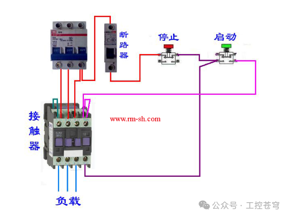
↑ Left side PLC terminals, right side buttons + contactor, distinguished by different colored wires
- PLC input terminals:
- Start button (green) → I0.0 (normally open contact, closes when pressed);
- Stop button (red) → I0.1 (normally closed contact, opens when pressed);
- Power supply: PLC L connects to 220V live wire, N connects to 220V neutral wire.
- PLC output terminals:
- Q0.0 → contactor coil A1 terminal;
- Contactor coil A2 terminal → 220V neutral wire (must be in series with the normally closed contact of the thermal relay, cutting off the coil power in case of overload).
2. Power circuit wiring (contactor and motor)
- Three-phase power (L1, L2, L3) → fuse (10A) → contactor main contacts (L1→T1, L2→T2, L3→T3) → thermal relay main contacts → motor connection terminals (U, V, W);
- Motor casing connected to ground wire (PE) to ensure safety.
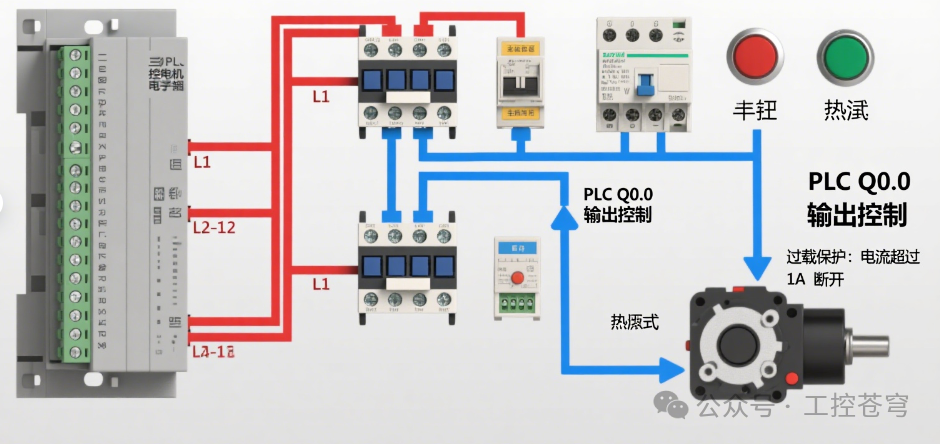 Use red wires to mark power lines and blue wires to mark control lines; label the contactor coil circuit as “PLC Q0.0 output control” and label the thermal relay as “Overload protection: disconnect at current over 1A”4. Program writing: Ladder diagram + step explanation (using TIA Portal V16 software)
The Siemens S7-200 SMART timer has 3 time bases (1ms, 10ms, 100ms), 2 hours = 7200 seconds = 7200000 milliseconds, choose the 100ms time base timer (T37/T38), set value = 7200000÷100=72000 for easier calculation.
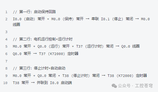
1. Overall program framework (divided into 3 parts)
① Start holding circuit: After pressing start, it continues to run even if the button is released
- Ladder logic: I0.0 (start) normally open + M0.0 (auxiliary relay, cycle state holding) normally open → in series with I0.1 (stop) normally closed → output M0.0 coil.
- Function: Pressing I0.0 sets M0.0 to 1 (self-locking); pressing I0.1 (normally closed becomes normally open) resets M0.0, interrupting the entire cycle.
② Running timing + stopping switch: The motor runs for 2 hours and then stops automatically
- Logic: M0.0 (cycle holding) normally open + Q0.0 (motor running) normally open → in series with T37 (running timer) normally closed → output Q0.0 coil;
- At the same time, Q0.0 normally open → triggers T37 timer (set value K72000, 100ms time base = 2 hours).
- Function: After M0.0 is set to 1, Q0.0 is energized (motor runs), T37 starts timing; after 2 hours, T37 normally closed becomes normally open, Q0.0 loses power (motor stops), T37 resets.
③ Stopping timing + running switch: The motor starts automatically after stopping for 2 hours
- Logic: M0.0 normally open + Q0.0 (motor stopped) normally closed → in series with T38 (stopping timer) normally closed → triggers T38 timer (set value K72000);
- T38 normally open → parallel to I0.0 start terminal.
- Function: After Q0.0 loses power, T38 starts timing; after 2 hours, T38 normally open becomes normally closed, equivalent to “automatically pressing the start button”, Q0.0 is energized again (motor starts), T38 resets, entering the next cycle.
2. Complete ladder diagram (simplified version)
5. Program download and debugging: 3-step verification of functionality
1. Download the program to the PLC
- Connect the PLC to the computer using a USB cable, open TIA Portal V16, select “Online” → “Download”, check “Program Blocks”, and click “Start Download”;
- After the download is complete, switch the PLC to “RUN” mode (operational mode).
2. Manual testing: First check if a single cycle works correctly
- Press the “Start” button (I0.0): PLC Q0.0 indicator light turns on → contactor engages (with a “click” sound) → motor runs;
- Observe the TIA Portal “Monitoring” interface: T37 timer value starts from 0 and increases until 72000 (2 hours), Q0.0 indicator light goes off → motor stops;
- T38 timer starts increasing to 72000 (2 hours), Q0.0 lights up again → motor starts, confirming that the single cycle works correctly.
3. Stop testing: Ensure emergency interruption is effective
- During the cycle, press the “Stop” button (I0.1): M0.0 resets → Q0.0 immediately goes off → motor stops, timer resets, cycle is interrupted;
- After releasing the stop button, you need to press start again for the cycle to restart (to avoid automatic operation after accidental touch).
6. Newbie pitfalls: 3 common problems + solutions
1. Timer timing is inaccurate?
- Reason: Incorrect time base selected (for example, using a 10ms time base, the set value of 72000 would become 720 seconds = 12 minutes);
- Solution: Check the timer properties in TIA Portal to confirm that T37/T38’s time base is “100ms”, set value = 72000.
2. Motor does not start?
- Troubleshooting steps:
① Check if the PLC Q0.0 indicator light is on: If not, check the program (Is M0.0 set to 1? Is T37 normally closed?); If it is on, check the contactor (Is there 220V voltage at the coil? Are the contacts oxidized?);
② Check the thermal relay: Is it tripped due to overload (Is the thermal relay reset button popped out? Pressing reset will fix it).
3. Cycle does not switch?
- Reason: T38 timer has not reset, preventing the next start from being triggered;
- Solution: In the program, parallel “Q0.0 normally open contact” to T38 (When Q0.0 is on, T38 resets), ensuring T38 starts timing from zero each time it runs.
7. Expansion: Want to change the cycle time? One step to complete
If you need to “run for 1 hour, stop for 3 hours”, just modify the set values of the two timers:
- Running timer T37: 1 hour = 3600000ms → set value = 3600000÷100=36000;
- Stopping timer T38: 3 hours = 10800000ms → set value = 10800000÷100=108000;
- No need to change other logic, flexible adaptation to different scenarios.
What other requirements have you encountered in intermittent control? For example, “multiple motors alternating cycles” or “timed delayed start”, feel free to leave a comment, and next time I will help you break down the corresponding PLC program!
If you found this helpful, please give a thumbs up and follow! ^_^