
This is Luojia Morning Repair‘s 281st post
Introduction
Three-dimensional printing (3D printing) technology, also known as additive manufacturing (AM), allows designers to obtain three-dimensional digital models through volumetric imaging technology or reverse engineering (RE). After obtaining the model, it is sliced into two-dimensional contours using computer-aided design (CAD) software. The DICOM files are then converted to STL format, and the 3D printer uses various additive manufacturing techniques to layer adhesive printing materials, photopolymerize, sinter, or melt them to form the final three-dimensional model.
The printing of three-dimensional models has been applied in many areas of dental restoration, including the production of models, wax patterns, surgical guides, and restorations (such as temporary restorations, crowns, inlays, onlays, veneers, and personalized abutments). Among these, surgical guides used in dental restoration refer to high-precision devices designed based on digital technologies, including medical imaging technologies (CBCT, MDCT, and MRI), digital impression techniques (intraoral scanning, laboratory scanning, and facial scanning), digital photography, and virtual articulator technology (electronic facebow). These guides are constructed from three-dimensional digital models of the patient’s jawbone, oral soft and hard tissues, facial morphology, and personalized occlusal information. Preoperative digital simulations of surgical plans are performed in software, and the guides are printed using CAD technology to assist the surgeon in achieving the desired operational goals during surgery. Common digital surgical guides in dental restoration include digital implant guides, digital crown lengthening guides, digital tooth preparation guides, and digital resin injection guides. Here, we will briefly outline the design of digital implant guides:
01
Digital Implant Surgical Guides
Digital implant guides are created by collecting CBCT scan data of the patient’s jawbone and obtaining three-dimensional data of the patient’s oral soft and hard tissues using scanning devices. Specialized dental software is used to virtually place the implants and design the surgical guides, which are then fabricated using 3D printing technology..
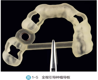
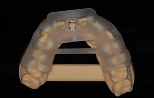
Classification: Implant surgical guides consist of two parts: the retention part and the guiding part. The main structure typically includes a guiding ring, retention pin channels, a covering denture structure, positioning check windows, and cooling windows. Based on the retention methods of the implant surgical guides, they can be classified into dental-supported implant guides, membrane-supported implant guides, and bone-supported implant guides. When creating bone-supported implant guides, the accuracy of the jawbone data reconstructed from the patient’s CBCT data may not be high enough, which can significantly affect the accuracy of the bone-supported guide’s positioning on the jawbone. Therefore, the implant accuracy using bone-supported guides is generally lower compared to other types of supporting guides.
According to the degree of guidance provided during implant placement, implant guides can also be divided into partial guidance implant guides and full guidance implant guides. Partial guidance implant guides only assist in the axial positioning of the implants without guiding the depth of implant placement; full guidance implant guides can accurately control the depth and axial positioning of the implants through the use of compatible navigation tools and the guidance of the implant guide.
02
Design of Digital Implant Surgical Guides
1. Data Preparation:
CBCT scan data (DICOM format) and three-dimensional data of oral soft and hard tissues (which can be obtained through traditional model fabrication followed by scanning or chairside intraoral scanning to create digital models in STL format). For cases with high aesthetic and occlusal functional requirements, it is also necessary to provide the patient’s smile photos and photos taken with an open mouth or use facial scanning data, personalized electronic facebow data, and radiographic dentures made for edentulous patients prior to surgery.
2. Steps for Designing the Implant Guide:
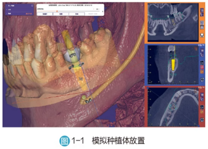
2.1 Import the patient’s oral soft and hard tissue scan data and CBCT scan data, adjusting different thresholds to obtain clear skeletal information and tooth morphology for three-dimensional reconstruction and defining the critical values of soft and hard tissues, setting the panoramic curve range according to the surgical plan.
2.2 Spatially match the CBCT scan data with the oral model scan data. If a radiographic denture has been previously made, the patient should wear it during the CBCT scan, and a separate CBCT scan of the radiographic denture should be performed for three-dimensional reconstruction. After reconstructing both sets of CBCT scan data, spatial matching is performed, and the software will display the matching results in different colors to indicate data matching accuracy. Additionally, a two-dimensional cross-sectional view will be shown in the auxiliary view window to demonstrate the spatial matching effect. At this point, the accuracy should be checked and evaluated to meet clinical surgical design requirements. If the matching error is large, manual adjustments can be made or threshold parameters can be adjusted for precise spatial matching again.
2.3 Before virtually placing the implants, mark special anatomical landmarks such as the mental foramen, mandibular nerve canal, incisor canal, and maxillary sinus area. When delineating the maxillary sinus area, the software can achieve sinus cavity separation by adjusting critical value parameters.
2.4 In the software, perform the virtual design of the final restoration, arranging teeth, placing implants, and retention pins. The completed solid diagnostic wax patterns can also be imported into the design software through scanning, guiding the placement of implants based on the final spatial position of the restoration. The ideal three-dimensional position of the implants must adhere to basic implant principles while considering the functional and aesthetic aspects of the restoration, the patient’s bone volume, and keratinized gingiva, achieving a balance of multiple factors. The selection and placement of the virtual implants must comprehensively consider the depth, angle, jawbone condition, and the spatial relationship between the final restoration and opposing teeth.
In the anterior region, the implant position should be slightly lingual, with the thickness of the buccal bone wall needing to be greater than 1mm and the thickness of the lingual bone wall needing to be greater than 2mm. Additionally, when performing immediate implant placement in the anterior region, a minimum gap of 2mm should be maintained between the buccal edge of the implant and the buccal bone wall of the extraction socket to ensure sufficient space for bone graft materials to maintain the buccal contour of the alveolar ridge and allow adequate blood clot retention for subsequent bone formation. The implant position should be centered in the edentulous gap or slightly distal while ensuring a safe distance. The ideal distance from the outer wall of the implant to the roots of adjacent teeth should be ≥2mm, with a minimum distance of ≥1.5mm, and the ideal distance between adjacent implants should be ≥3mm. The axial orientation of the implant should be positioned in the screw channel at the location of the lingual ridge of the final restoration, with the bone-level implant platform ideally located at a depth of 3-4mm from the mid-point of the buccal gingival margin. For immediate implant placement in the anterior region, the implant should penetrate 3-4mm into the bone tissue below the apex of the extraction socket.
In the posterior region, the buccal-lingual thickness of the implant’s outer wall should be greater than 1mm, and the mesial-distal position should be aligned with the central fossae of the adjacent teeth, centered in the edentulous gap. The ideal distances and minimum spacing between implants and adjacent teeth should be consistent with those in the anterior region to avoid resorption of the adjacent alveolar bone and the risk of papilla recession. The long axis of the posterior implant should be perpendicular to the occlusal plane and directed towards the functional cusp of the opposing teeth to minimize tensile and shear forces during occlusion, thereby reducing lateral forces. The bone-level implant platform should be flush with the bone surface or located 0.5-1mm below the bone surface, with the root end of the implant being ≥2mm away from special anatomical landmarks.
For multiple adjacent tooth loss, the position of the implants should reference the final restoration position and select the area with the best bone volume. If the width of the alveolar ridge in the buccal-lingual direction and the morphology of the artificial crown allow, more than three consecutive implants should form a planar layout.
For edentulous arches, if choosing implant-supported overdentures, at least four implants should be placed in the maxilla and at least two in the mandible due to the more porous bone quality in the maxilla. If choosing implant-supported fixed dentures, at least six implants should be placed in the maxilla and at least four in the mandible. The implants should be distributed in a planar manner, and they should be as parallel as possible. Angle correction abutments can be used to adjust the parallelism of the implants to change the exit position of the screw holes. When there is insufficient bone volume in the posterior region, implants can be placed at an angle. In the restoration design, short dental arches or cantilever designs can be made, but the cantilever distance should be controlled within 1.5 times the distance between the two anterior implants and the two terminal implants.
To enhance the retention stability of membrane-supported and bone-supported surgical guides, retention pins are usually required. Typically, 3-5 retention pins are set, commonly distributed on the buccal-labial side in a fan shape. When placing retention pins, they should enter the cortical bone from one side, with the tips of the pins embedded 3-6mm into the bone, while avoiding damage to the nerves or entering the maxillary sinus on the opposite side. The safety distance between the retention pins and the roots of adjacent teeth and implants is usually set to 1.5mm.
2.5 Design the guiding ring of the implant guide. During the implant surgery, the placement of the implants is controlled by the guiding ring of the implant guide. The spatial position of the guiding ring in a full guidance implant guide is determined by the predetermined implant placement position, with only a few fixed heights available for selection. When selecting the height for placing the guiding ring, it should be as close to the implant as possible to improve the accuracy of the implant surgery. Care should also be taken to avoid the guiding ring encroaching on the patient’s soft and hard tissues and to maintain the positional relationship with adjacent teeth to prevent obstruction of the implant machine handle due to insufficient space during the surgery. If using a partial guidance implant guide, a third-party universal guiding ring can be selected, or only the guiding ring for the pilot drill can be used. Universal guiding rings or pilot drill guiding rings cannot accurately position the depth of implant placement; they can only determine the direction of placement.
When designing the guide, it is preferable to design the gap space between the finished guiding ring and the retention pin sleeve to ensure smooth adhesion of the guiding ring to the guide later. Additionally, parameters that affect the positioning of the guiding ring should be cleared.
2.6 Determine the positioning path of the guide and remove any soft and hard tissue undercuts that affect the positioning of the guide.
2.7 Design the coverage support range of the guide. The edge range of the guide should be designed based on the remaining teeth in the patient’s mouth and the retention form of the guide; dental-supported implant guides can be designed in a cross-arch style, while edentulous arch guides should reference the extension range of the complete denture base to enhance the stability of the guide in the patient’s mouth.
2.8 Design the positioning check windows. Typically, at least one check window should be set at the mesial and distal parts of the guiding ring, with the window position usually set at the cusp tips.
2.9 Design cooling windows. The setting of cooling windows can increase the exposure area of the surgical site, enhance cooling effects, and also serve as a channel for local infiltration anesthesia.
2.10 Design reinforcement rods. The addition of reinforcement rods can reduce the deformation of the surgical guide during printing and increase the strength of the guide.
Once the main structures are designed, the data for the implant surgical guide can be generated, and the STL format guide file can be output for printing using a 3D printer, with the guiding ring assembled to the guide through adhesion.
03
Printing Technology for Surgical Guides
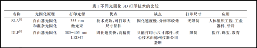
1. Guide Materials:The materials used for 3D printing mainly include wax patterns, resin materials, metal materials, and ceramic materials, which can be selected based on the target to be printed. In the field of restoration guides, resin materials, particularly photosensitive resins (Ultraviolet rays, UV), are commonly used. Photosensitive resins are generally in liquid form and consist of three main components: reactive monomers, oligomers, and photoinitiators, along with a small amount of other additives. Under specific wavelengths of light (usually 380-405 nm), the photoinitiator is activated, releasing free radicals or reactive ions, promoting the rapid reaction of monomers and oligomers, forming long cross-linked polymer chains, and achieving the transition from liquid resin to solid three-dimensional structures.
2. Classification of Resin Implant Guides:Photosensitive resins can be classified into three types based on the mechanism of the initiators: free radical photosensitive resins, cationic photosensitive resins, and free radical-cationic hybrid photosensitive resins.
2.1 Free Radical Photosensitive Resins
These are commonly used materials in 3D printing, based on acrylate prepolymers. Under UV light, the photoinitiator decomposes to generate free radicals, initiating the cleavage of double bonds in the acrylate, driving the polymerization reaction to form high molecular weight polymers. These resins have advantages such as fast curing speed and low raw material costs. However, they also have significant drawbacks, including substantial volumetric shrinkage and internal stress that can lead to product warping, requiring secondary curing, high shrinkage rates during curing, and relatively low curing reaction rates.
2.2 Cationic Photosensitive Resins
Their prepolymers mainly consist of epoxy compounds and vinyl ethers, which undergo ring-opening polymerization under the action of cationic photoinitiators, forming stable cured products. Their advantages include low volumetric shrinkage, high reaction degree, and resistance to oxygen inhibition, ensuring dimensional stability and excellent mechanical properties of the printed objects. However, their raw material costs are relatively high, and the high viscosity of epoxy resins slows down the light curing rate, requiring the addition of low-viscosity reactive components for improvement.
2.3 Free Radical-Cationic Hybrid Photosensitive Resins (i.e., acrylate-epoxy hybrid systems)
This is a new type of material developed in recent years, containing components that can generate both free radicals and cations in the prepolymer. During the light curing process, both polymerization mechanisms operate simultaneously, achieving a perfect balance of light initiation efficiency, volumetric change control, and performance optimization. Free radical-cationic hybrid photosensitive resins have advantages such as high cost-performance ratio, moderate viscosity, strong mechanical properties, and good mechanical performance, making them very suitable for application in 3D printing technology.
3. 3D Printing Processing Technologies
Based on different printing principles, 3D printing technologies can be divided into stereolithography (SLA), material jetting, material extrusion, binder jetting, powder bed fusion, sheet lamination, and directed energy deposition. In the field of implant guides, 3D printing resin technology mainly applies stereolithography (SLA), digital light processing (DLP), and digital droplet jetting technologies such as polymer jetting.
3.1 Stereolithography (SLA) Technology
SLA technology involves irradiating the surface of liquid photosensitive resin according to a designed scanning path, curing the resin layer by layer into the corresponding shape, resulting in a three-dimensional solid model through layer stacking.
SLA advantages: mature technology and stable system; printing accuracy can reach micron-level, meeting the requirements for digital guide production; good surface quality, capable of printing fine structures.
SLA disadvantages: photosensitive resins can cause skin allergies and environmental pollution; cured photosensitive resins are relatively brittle and prone to breakage, and the formed parts can easily deform. Support structures need to be set during printing, and removing them after curing can easily damage the surface of the formed parts; secondary curing treatment is required for the formed parts.
3.2 Digital Light Processing (DLP) Technology
DLP technology, a form of “liquid resin photopolymerization,” has a curing principle similar to SLA, but instead of using lasers, it employs a high-resolution DLP projection system. Selective UV light with a wavelength of 405nm is projected onto the photosensitive resin to cure it. Unlike the linear scanning of lasers in SLA, DLP can simultaneously illuminate an entire surface for overall curing.
DLP advantages: fast single-layer curing speed; high printing accuracy.
DLP disadvantages: UV light overflow from DLP 3D printing devices can cause harm to humans; the variety of DLP photosensitive raw materials is limited, and their performance has certain gaps compared to existing engineering plastics, leading to application limitations; lower resolution when printing full models.
3.3 Polymer Jetting Technology
Polymer jetting technology, similar to inkjet printing, involves spraying liquid photopolymer layers onto the printing platform and immediately curing them with UV light, eliminating the need for subsequent curing. During printing, a dual nozzle is used, one for spraying the build material and the other for spraying support material. The support material is jetted alongside the selected model material to support models with overhangs and complex geometries, which can be removed post-printing using high-pressure water or heat without damaging the surface of the formed parts.
Advantages: The adjustment of the droplet size properties of the nozzles can achieve resolutions up to 1000 dpi; high jetting frequency allows for rapid printing; droplet diameters can be controlled at the micrometer level, with high uniformity, and the printing thickness can be controlled at around 16 microns; multiple materials can be printed simultaneously, allowing for the printing of multiple colors in one go.
Disadvantages: The printing platform of this technology’s 3D printers is relatively large, and thorough cleaning of the delivery pipes is required when changing materials, leading to significant material waste; preheating is also necessary before printing, as the liquid in the nozzles must melt before printing, which takes time; dual nozzles reduce printing costs and increase printing speed, allowing for flexible selection of support materials.
04
Precautions for Clinical Use of Implant Guides
1. Avoid light and high temperatures; use the guide as soon as possible after printing to prevent deformation and changes in the patient’s oral condition.
2. Surgical guides printed with photosensitive resin are not suitable for high-temperature and high-pressure sterilization. Typically, they can be soaked in 75% ethanol or iodine for disinfection half an hour before surgery, and during surgery, they can be rinsed with saline.
3. After disinfection, perform an intraoral trial fit of the guide to check if the pre-set window areas of the guide fit well with the teeth or other tissues. If not, adjust the obstructing areas and rinse for a trial fit. If it still does not fit well after adjustment, a new surgical guide needs to be made.
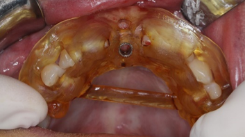
(Images provided by Dr. Zhu Xiao, Associate Chief Physician of the Department of Prosthodontics, Wuhan University)
4. Membrane-supported and bone-supported implant surgical guides need to be guided by occlusion. When positioning the guide, it is necessary to check if the occlusion is correct, if there is any displacement, and whether the guide is stable. Check for pressure points on the tissue surface, and ensure that the position of the retention pins is not interfered with by the buccal-labial muscles and is not too far back to complete the preparation of the retention pin channels.
5. During the trial fit, the stability of the guide should also be checked, especially for mixed-support and membrane-supported guides, to avoid any shaking during the implant surgery that could affect the accuracy of the implant placement. Additionally, check if the selected tools are appropriate and do not interfere with the surgical operation or compress the buccal-labial muscles.
6. Since the mucosa may thicken after anesthesia, this can affect the accuracy of the guide’s positioning and, consequently, the precision of implant placement. Therefore, it is essential to choose the appropriate anesthesia site and timing for guide positioning. Typically, after stabilizing the guide, local infiltration anesthesia should be performed at the sites where retention pins will be placed, followed by the preparation and placement of the retention pins to ensure correct positioning of the guide. Anesthesia for the implant area can then be performed through the reserved check windows and cooling windows of the guide before proceeding with the implant surgery. Alternatively, local anesthesia can be performed first, and once the anesthetic effect subsides, the guide can be repositioned, but this method requires careful control of the timing for repositioning the surgical guide.
7. Throughout the implant surgery guided by the guide, the stability of the guide must be ensured; otherwise, it may lead to deviations in the implant placement position. During the surgery, the three-dimensional position of the implant should be checked, and if significant deviations are found, timely corrections should be made.
8. Compared to traditional freehand implant surgeries, surgeries guided by guides should pay more attention to cooling the surgical area. This can typically be achieved by reserving cooling windows on the guide, increasing the water output of the implant machine head, or having an assistant continuously apply additional water cooling to the surgical area. During the procedure, it is necessary to repeatedly lift and pause for 2-3 seconds to allow the cooling water to adequately wash and cool the surgical area and the implant site to prevent excessive temperature, which could cause bone burns.
References
[1] Dong Bo. (2024). Standards for 3D Printing of Dental Surgical Guides. China Medical Science and Technology Press. ISBN 9787521442786.
[2] France, A. K. (2016). 3D Printing from Beginner to Expert (Color Illustrated Edition). Zhang Tianlei, Zheng Siyu, Li Shuzhen, Wang Xin, Trans. Beijing: People’s Posts and Telecommunications Press.
[3] Hojasteh, A. K. (2025). New Intelligent Technologies in Oral and Maxillofacial Surgery. Sun Zhijun, Leng Weidong, Hu Chuanyu, Trans. Beijing: China Science and Technology Press.
[4] Wang Xuanqi, Zhang Jie, Li Fenglan. Current Applications of Photocurable 3D Printing Technology in Fixed Restoration. Journal of Oral and Maxillofacial Rehabilitation, 2025, 26(01): 68-73. DOI:10.19748/j.cn.kqxf.1009-3761.2025.1.012.
[5] Sun Yuchun, Li Rong, Zhou Yongsheng, et al. Applications of 3D Printing in the Field of Dental Restoration. Chinese Journal of Oral Medicine, 2017, 52(6): 381-385. DOI:10.3760/cma.j.issn.1002-0098.2017.06.013
[6] Zhang Qianqian, Chen Xin, Zhao Yuwei, et al. Applications of 3D Printing in Aesthetic Dental Restoration. West China Journal of Stomatology, 2018, 36(06): 656-661.


Author: Yao Lihao
Advisors: Zhao Yi, Song Fangfang
Editor: Dong Kai

Welcome to follow our public account: luojiachenxiu
Regularly publishingdental restoration cutting-edge dynamics
Long press to identify the QR code in the image to follow
Please indicate the source when reprinting


Scan to interact with us

If you find it useful, click here