
Click the blue text to follow us

Specific Functions Implemented
Composed of STC89C52 microcontroller + LCD1602 display + ADC0832 module + buzzer + DHT11 temperature and humidity sensor + smoke sensor + LED + buttons.
Specific Functions:
1. The first line of the LCD1602 displays the current smoke value, and the second line displays the current temperature and humidity values;
2. Allows setting of upper and lower limit alarm values for smoke, temperature, and humidity. There are 4 buttons: reset button, decrease button, increase button, and set button; the set parameters are saved in the STC microcontroller’s memory, so there is no need to reset them upon power-up;
3. When the smoke value exceeds the set alarm value or the temperature and humidity exceed the upper and lower limits, the buzzer and indicator light will issue an audible and visual alarm;
4. When the temperature and humidity values are below or above the set range, the corresponding indicator light will turn on, and the buzzer will alarm;
5. When all three conditions of high smoke, high temperature, and low humidity are met, the relay will be activated to control the motor to indicate extinguishing.
System Functional Requirements and Design Scheme
2.1 System Design Requirements
To achieve real-time display of temperature, humidity, and smoke, and timely alarms to reduce fire hazards, this paper will implement the following design requirements:
(1) Accurate and real-time detection of temperature, humidity, and smoke values in the villa;
(2) Direct and clear display of measured temperature, humidity, and smoke concentration values;
(4) Ability to implement automatic fire alarm;
(5) Simple operation, complete functions, and high accuracy.
As shown in the figure.
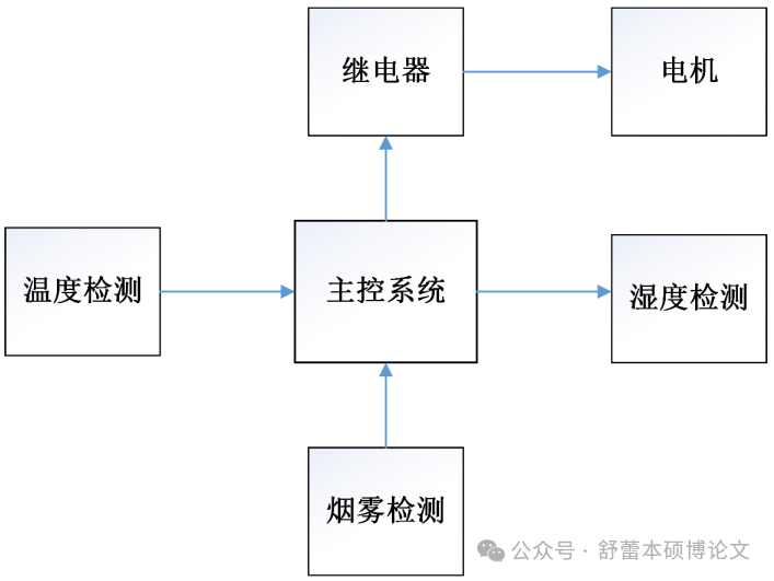
Hardware Design
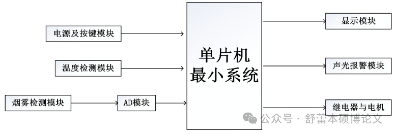
The figure shows the hardware design scheme of this system. Specifically, the hardware circuit consists of the following modules:
(1) Minimum system of the microcontroller. Used to drive and control other modules to achieve overall functionality, centered around the STC89C51 microcontroller, supplemented by a reset circuit and crystal oscillator circuit.
(2) Signal acquisition circuit. Responsible for collecting the data to be monitored. In this design, the signal acquisition circuit consists of temperature acquisition circuit, smoke acquisition circuit, and infrared acquisition circuit.
(3) AD conversion circuit. Composed of the ADC0832 module, which is connected to the sensor and microcontroller chip, responsible for converting analog values to digital quantities and sending them to the microcontroller.
(4) Button and display circuit. The display circuit is used to show relevant data, and the button circuit is used to control the chip to achieve related functions, directly connected to the microcontroller.
3.1 Main Controller Circuit Design
The minimum system of the microcontroller is the most basic and essential part of microcontroller expansion and application, generally composed of the following circuits, and is the core of the entire design, ensuring the expansion and realization of other functions based on the microcontroller. As shown in the figure.
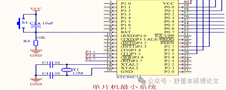
Reset circuit: The reset circuit is the most basic and important circuit in microcontroller applications, used to handle emergencies such as microcontroller malfunction. The reset circuit is divided into power-off reset and button reset. This paper uses button reset, which works as follows: when the reset port of the microcontroller is at a high level, the code in the microcontroller will not be executed. Initially, when powered on, the capacitor is not fully charged, and the reset port is at a high level, preventing program errors caused by running the program immediately upon power-up. When the capacitor is fully charged, the reset port becomes low, and the program starts running. Additionally, when the button is pressed, the microcontroller is in a reset state.
Crystal oscillator circuit: The crystal oscillator circuit provides the essential clock frequency for the microcontroller, necessary for data transmission and the working timing of the microcontroller. This graduation project provides an 11.0592MHz clock frequency. The microcontroller chip’s XTAL1 (pin 19) and XTAL2 (pin 18) form the clock pins of the microcontroller, creating a stable oscillation circuit to ensure the normal operation of the microcontroller; the crystal oscillator circuit uses two 20pf capacitors.
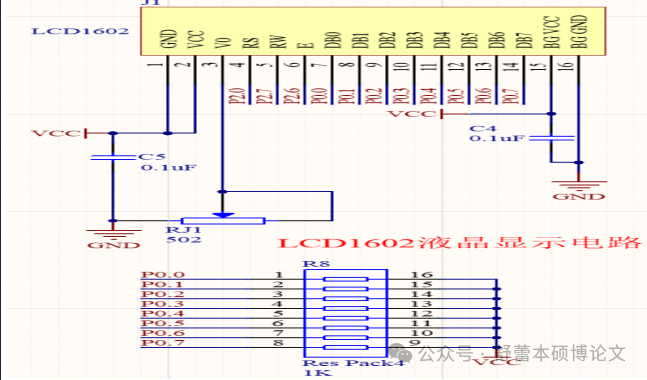
3.2 LCD1602 Display Module Design
This system uses the LCD1602 liquid crystal display to show temperature, humidity, and smoke values. It is well-known that in microcontroller design, LED digital tubes or LCD displays are generally used to display data, and the LCD display has prominent characteristics, displaying data more clearly and with lower power consumption, making it suitable for this design. The following figure shows the pins of the LCD display. The pin descriptions are as follows:
Pin 1: VSS is the ground power supply.
Pin 2: VDD connects to the 5V positive power supply.
Pin 3: V0 connects to the positive power supply through a 10K resistor.
Pin 4: RS is the register select; in high state, it is the data register, and in low state, it is the instruction register.
Pin 5: R/W is the read/write signal line; in high state, it performs read operations, and in low state, it performs write operations.
Pin 6: E is the enable pin; when it transitions from high to low, the LCD module starts executing code.
Pins 7-14: D0-D7 are data input pins. Pin 15: positive terminal of the backlight.
3.3 Temperature and Humidity Sensor Module Design
The temperature sensor’s port 1 is grounded, ports 2 and 3 connect to the power supply and microcontroller through a 10K pull-up resistor, and the collected digital signal is sent directly to the microcontroller for processing and display. The liquid level sensor and flow sensor need to be externally connected through pin headers, as shown in the figure.

Software Design
Based on the design requirements in this paper, the specific functions to be implemented through software programming on the basis of the hardware circuit design in Chapter 3 are:
(1) Drive each module to work, realize temperature collection and display, and smoke concentration collection and AD conversion display;
(2) Button setting function. Implement temperature and humidity alarm threshold settings, smoke alarm threshold settings, motor drive, etc.;
(3) Alarm function implementation. Implement audible and visual alarms for high temperature, low temperature, high humidity, low humidity, and high smoke concentration;
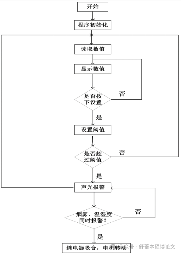
(4) Relay control of the motor. When the conditions of high smoke, high temperature, and low humidity are simultaneously met, control the relay to activate the motor, indicating extinguishing. The design flow is shown in Figure 4-1.
Simulation Implementation
5.1 Simulation Implementation 5.1.1 Simulation Circuit Diagram
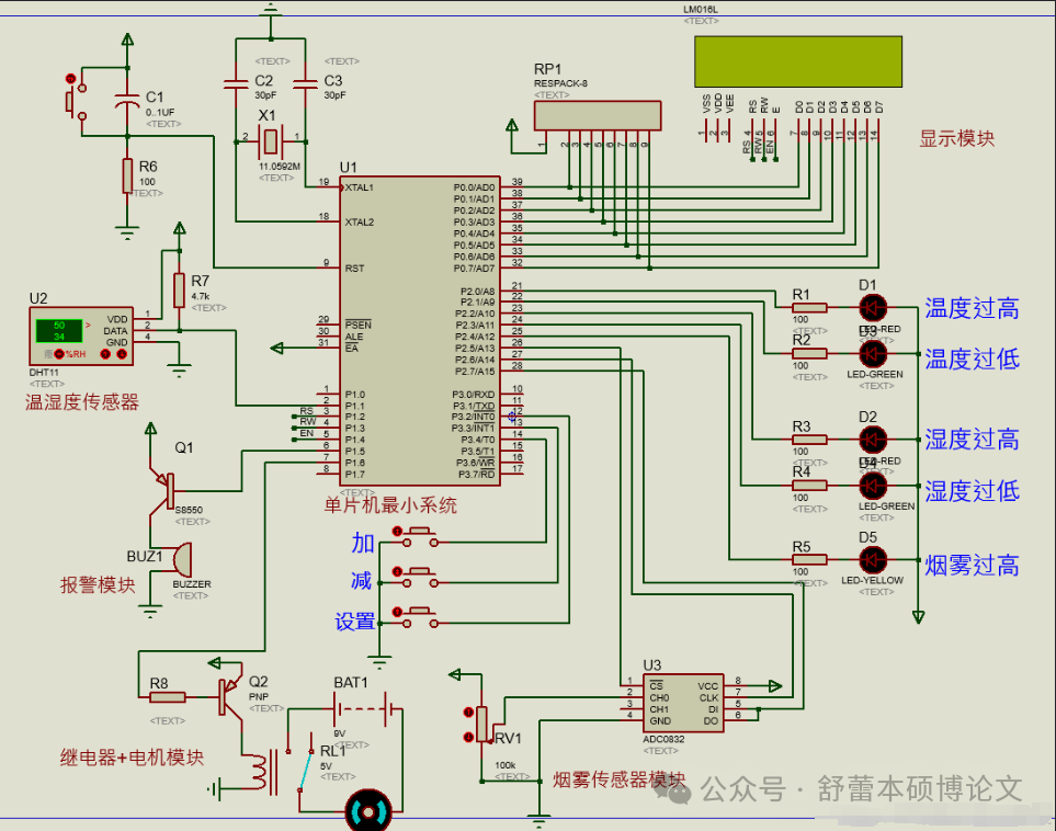
This system uses the protues8.7 designed simulation schematic diagram as shown.
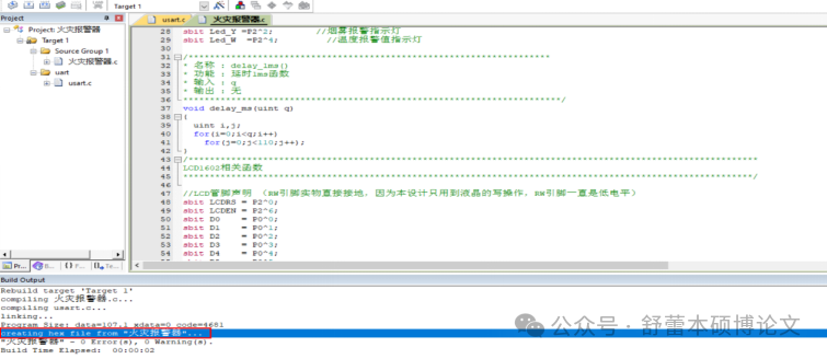
Based on the software design ideas in Chapter 4, combined with simulation requirements, we will write the simulation design C code using KEIL5, with detailed comments. Then, we click “create HEX file” and compile the program again, which will generate the HEX burning file, as shown.
Next, we open the simulation schematic and burn the produced “HEX” file into the microcontroller chip, click start simulation, and the relevant simulation can be realized.
5.1.2 Simulation Results
(1) Display of temperature and humidity values and smoke values
(2) Setting of temperature and humidity alarm thresholds and smoke alarm thresholds
(3) Automatic fire alarm
(5) Automatic extinguishing
5.2 Test Situation Analysis
After a series of simulation tests, the “Intelligent Home Control System Based on 51 Microcontroller” designed in this paper meets the system requirements in Section 2.1, specifically simulating the following functions:
(1) Temperature and humidity measurement and display are stable and accurate; smoke measurement and display are stable and accurate;
(2) The temperature and humidity alarm thresholds can be set via buttons, and when the measured temperature and humidity exceed the set thresholds, the alarm indicator light flashes, and the buzzer alarms; the smoke alarm threshold can also be set via buttons, and when the measured smoke concentration exceeds the set threshold, the smoke alarm indicator light flashes, and the buzzer alarms;
(3) When the conditions of high smoke, high temperature, and low humidity are simultaneously met, control the relay to activate the motor, indicating extinguishing.

Scan to get more graduation design cases!
Free consultation for thesis-related questions!