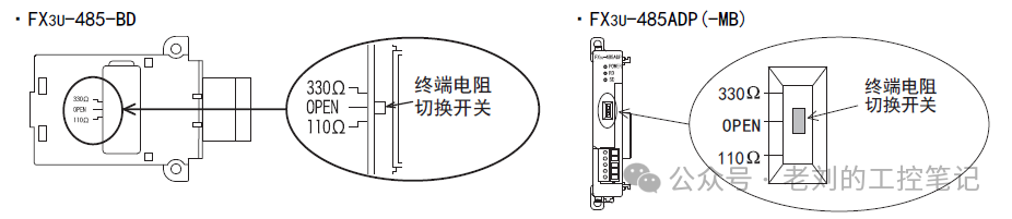
The Mitsubishi N:N network communication allows for simple and cost-effective information exchange between multiple PLCs without the need for complex communication parameter settings.1、Function OverviewThe Mitsubishi FX series PLCs support communication between up to 8 PLCs. After establishing communication, a shared area is automatically created within the 8 PLCs, enabling device interconnection and signal transmission.The N:N network supports communication across series, from the FX0N series to the FX3U series. This protocol uses RS-485 specifications for transmission, as detailed in the image below: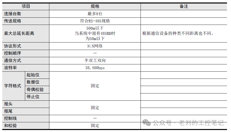 2、WiringWhen wiring, it is essential to connect terminal resistors at both ends (to reduce signal reflection in the communication cable), with a terminal resistor specification of 110Ω, 1/2W.Some communication modules have built-in terminal resistors, which can be switched directly as shown in the image below:
 The communication wiring diagram is shown in the image below (it is recommended to use twisted pair cables to enhance anti-interference capability):
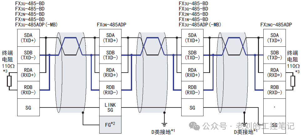 That is: SDA and RDA are shorted and connected to the SDA and RDA of another unit.3、Example Program (Three FX3)The soft component mapping corresponding to different N:N network modes is shown in the image below.
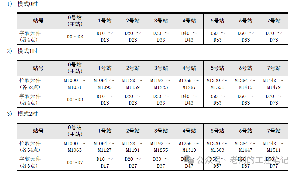 When mode 0 is selected, if the master station modifies the values of D0-D3, the values of D0-D3 at stations 1-7 will also change accordingly. Similarly, if station 1 changes the values of D10-D13, the values at the master station and stations 2-7 will also change.Note: When the master station changes the data of D0, the value of D0 will not be updated to the slave station in the same scan, so please be cautious when cyclically updating data.Communication Parameter Setting ExampleMaster Station Program Example:
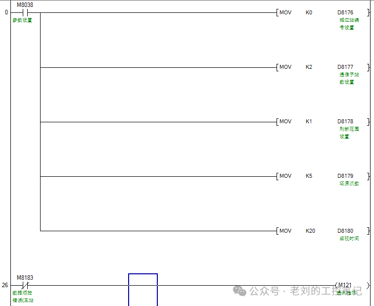 Slave Station 1:
 Slave Station 2:
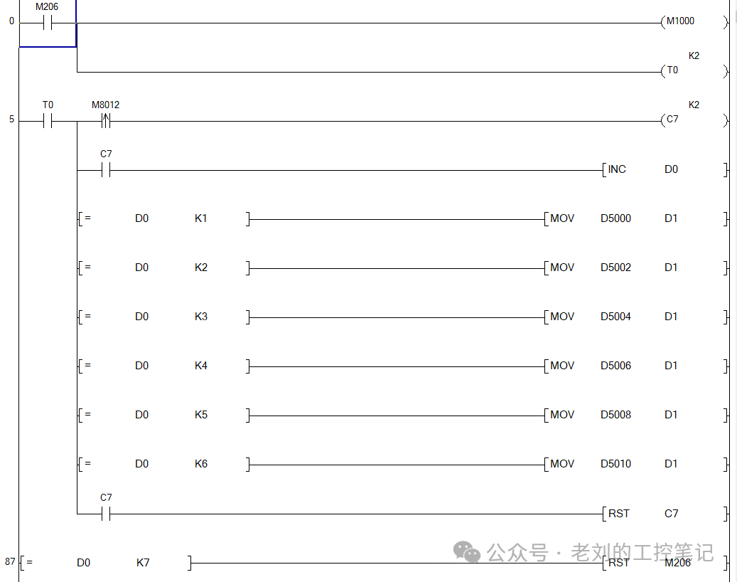
 Data Interaction ExampleAs mentioned above, when the master station’s data changes, the slave station’s data does not change immediately; there will be a delay. So how should we synchronize parameters? As shown below, synchronize the master station’s D5000-D5010 to slave station 1’s D5000-D5010.Master station program, as shown in the image below, M206 is the start synchronization button, and M1000 is the start synchronization flag.
 Slave station 1 program is shown in the image below.
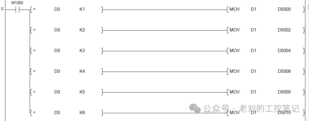 Any communication will have delays, and when synchronizing parameters, it is important to consider the delay effect between the two stations.If you have any questions regarding communication data transmission, feel free to leave a comment for discussion~