Recently, a friend of mine used Siemens’ safety PLC for the first time. Since most safety-related content in Siemens PLC is in English, there were many areas that were not very clear. He reached out to me for discussion and learning. Indeed, using the safety features of Siemens PLC requires some time for beginners.
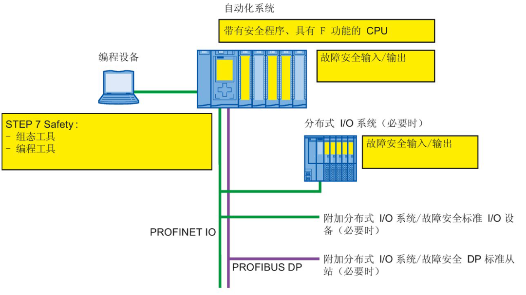 So today, I have some time to write a simple tutorial on using Siemens safety PLC.The link below is a previous example of configuring the S7-1500F CPU with the ET200SP safety module configuration process, which you can check out first.This article mainly discusses the detailed explanation of parameters when configuring the ET200SP safety input/output modules.
F-DI Module F-Parameters
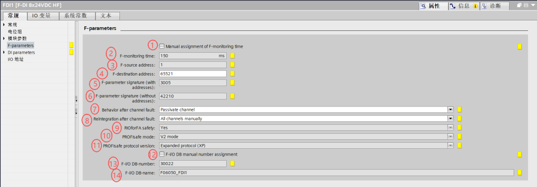 1.Manual assignment of F-monitoring time
The option to manually assign the F-monitoring time is generally not checked, and the default is to use the system-assigned time.
2. F-monitoring time
The F-monitoring time value range is 1-65535. If the Manual assignment of F-monitoring time option is not checked, the default is 150ms.
3. F-source address
The F-source address is the source address for sending safety data in PROFIsafe communication, used for data addressing. The value range is 1-65534, depending on the parameter allocation of the F-CPU.
4. F-destination address
The F-destination address is the destination address for receiving safety data in PROFIsafe communication, enabling directed transmission. The value range is 1-65534, and it is recommended to use the value assigned by the F-system.
5/6. F-parameter signature (with addresses)
The F-parameter signature, with and without addresses, is used to verify parameter integrity and prevent unauthorized tampering. The value range is 0-65535, calculated automatically by the F-system.
7.Behavior after channel fault
Behavior after a channel fault
| Option | Explanation |
| Passivate the entire module |
Disables the entire module; when any channel of this module fails, all channels of the entire module will be disabled. |
| Passivate channel |
|
8. Reintegration after channel fault
Recovery methods after channel fault
| Option | Explanation |
| Adjustable | Configurable recovery strategy: supports custom automatic/manual recovery rules for single or multiple channels based on the scenario. |
| All channels automatically |
All channels automatically recover: after troubleshooting, all channels of the module automatically return to normal operation (safety risks must be strictly assessed). |
| All channels manually | All channels manually recover: all channels must be manually operated to return to operation after a fault (highest safety, commonly used in high-risk scenarios). |
9. RlO for FA safety
| Option | Explanation |
| YES | Enables remote I/O mode, supporting communication and control of remote safety devices, suitable for distributed safety architecture. |
| NO | Does not use a remote I/O architecture for safety communication in factory automation scenarios; safety data transmission and control are only conducted within the local architecture. |
10.PROFIsafe mode
PROFIsafe communication mode is V2 mode. PROFIsafe is Siemens’ safety communication protocol, and V2 mode has optimizations in functionality and performance compared to the earlier V1 mode, making it one of the mainstream modes for ensuring the reliability and real-time transmission of safety data.
11. PROFIsafe protocol version
PROFIsafe protocol version
| Option | Explanation |
| Expanded protocol (XP) | Expanded protocol version, enhancing communication reliability, fault detection capability, and functional extensibility. |
| Loop-back extension (LP) | Loop-back extension protocol version, supporting loop-back testing functionality to verify the integrity of the communication link. |
12. F-I/O DB manual number assignment
Whether to manually assign F-I/O data block (DB) numbers. If checked, the F-I/O DB-number is manually set; if not checked, the system assigns automatically.
13. F-I/O DB-number
F-I/O data block number. Used to store module safety I/O data, called by number in the program.
14. F-I/O DB-name
F-I/O data block name. Used to identify the data block for easier program recognition and management.
Sensor power supply testing
Can test whether the sensor power supply is short-circuited or crossed.
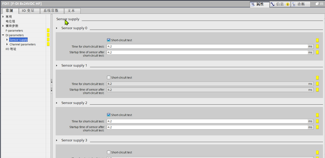
Short-circuit test
If this option is checked, the system will perform short-circuit detection on the corresponding sensor power circuit to determine if there is a short-circuit fault, ensuring circuit safety.
Time for short-circuit test
Set the duration of the short-circuit test.
Startup time of sensor after short-circuit test
After the short-circuit test is completed, the sensor needs to wait for this duration before starting to work. This setting allows the circuit to have a stable recovery time after testing, ensuring normal sensor operation.
Channel parameters
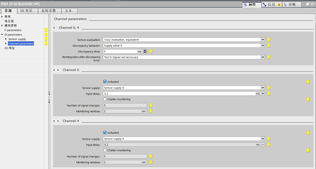
Sensor evaluation
There are three types of sensor evaluation methods.
-
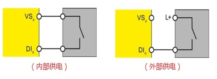
1oo1 evaluation
Using one input channel connected to a single-channel sensor, the wiring is as shown below.
-
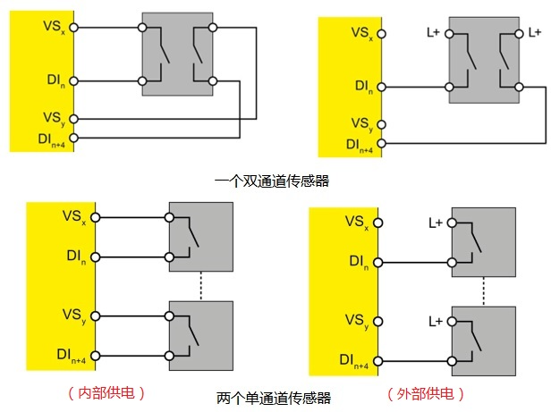
1oo2 evaluation – equivalent
Using two input channels connected to an equivalent dual-channel sensor or two single-channel sensors. The module will compare the input signals of the two channels (e.g., channel 0 and channel 4) within the channel group. Only when the signals of both channels meet the equivalent safety judgment rules will the signal be considered valid, thus enhancing the safety and reliability of signal acquisition and avoiding misjudgment due to a single channel failure.
-
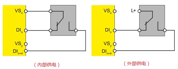
1oo2 evaluation – non-equivalent
Two channels are connected to sensors with opposite levels (one normally open contact + one normally closed contact), meaning one is 1 and the other is 0. The wiring is as shown below. If the module detects that the signals of the two channels are the same, it will trigger an alarm and enter a passive state.
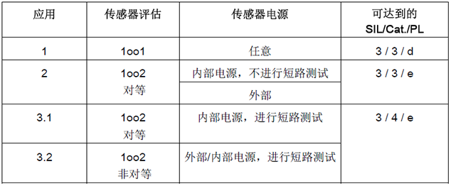
The safety module needs to adopt different wiring methods and parameter settings based on the safety level required by the application. The table below lists the minimum conditions that must be met to achieve the corresponding safety category.
Discrepancy behavior
Set the response strategy when the module detects discrepancies between channel signals.
| Option | Explanation |
| Supply last valid value | When a discrepancy between channel signals is detected, the module will use the last valid value as output or for subsequent logical operations. This helps maintain stable operation based on the previously valid signal during brief discrepancies, avoiding unnecessary fluctuations or malfunctions. |
| Supply value 0 | When a discrepancy between channel signals is detected, the module will output or use value 0 for subsequent logic. Value 0 typically corresponds to a safe state (e.g., equipment stopped, valve closed, etc.), ensuring that in the event of a signal discrepancy that may indicate a fault, the system enters a safe and reliable state, safeguarding industrial production and other scenarios. |
Discrepancy time
Set the time threshold for allowing discrepancies between the signals of two channels within the channel group. If the discrepancy duration exceeds 5 milliseconds, the module will determine it as an abnormal situation and trigger subsequent discrepancy response actions.
Reintegration after discrepancy error
| Option | Explanation |
| Test 0 – Signal not necessary | After a discrepancy error occurs, if reintegration (i.e., restoring the channel to normal working state) is desired, no “Test 0 signal” operation is required. In other words, the module can directly attempt to restore the channel’s normal operation without an additional 0 signal testing step to verify the channel status, allowing for a quicker recovery of channel functionality. |
| Test 0 – Signal necessary | After a discrepancy error occurs, if reintegration is desired, the “Test 0 signal” operation must be performed. Only when the Test 0 signal passes (i.e., a compliant 0 signal is detected) will the channel return to normal working state. This method is stricter and can further ensure that the channel is in a reliable state when resuming work, avoiding subsequent issues due to channel anomalies, but the recovery process will take slightly longer due to the additional testing step. |
Input module point parameter configuration
- ActivatedChecking indicates that this channel is enabled and can normally receive and process input signals.
- Sensor supplySelect “Sensor supply 0-7” to specify the sensor power circuit supplying power to this channel. If internal power is selected, thenExternal sensor supply cannot be checked, and the power test option cannot be selected.
-
Input delay
After the input signal enters the module, it must undergo a delay of the set time before further processing, used to filter out high-frequency interference and stabilize the signal.
- Chatter monitoringNot checked means that the monitoring function for input signal “chatter” (rapid irregular fluctuations) is not enabled.
-
Number of signal changes
Enable chatter monitoring; this parameter is the threshold for the number of signal changes allowed within the “monitoring window”.
-
Monitoring window
If chatter monitoring is enabled, this parameter is the length of the time window for chatter monitoring. The module will count the number of signal changes within the set time to determine if there is a chatter anomaly.
F-DO module F-parameters are basically consistent with F-DI.
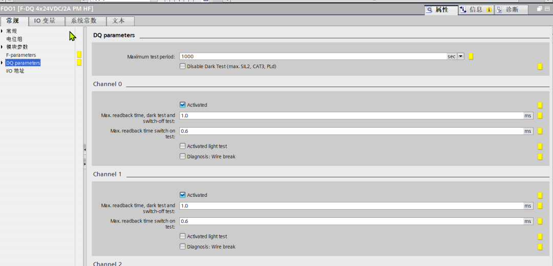
The F-DO module mainly explainsChannel parameters
DQ parameters
-
Maximum test period
Indicates the maximum time interval for the module to perform self-tests (e.g., hardware diagnostics, signal verification). The module will perform at least one test within the set time to ensure the reliability of output functions.
-
Disable Dark Test (max. SIL2, CAT3, PLe)
Not checked means that “Dark Test” is enabled (temporarily disabling tests, a mechanism for detecting latent faults in output modules). If checked, this test function will be disabled, and the module’s safety level can only reach SIL2, CAT3, PLe level.
(SIL is Safety Integrity Level, CAT is Category, PLe is Performance Level, all are grading standards in the field of industrial safety)
Output module point parameter configuration
-
Activated
Checking indicates that this channel is enabled and can normally perform output functions.
- Max. readback time, dark test and switch-off test
Indicates the maximum time limit for the module to read back and verify output signals during the temporary disable test (a mechanism for detecting latent faults) and switch-off test (verifying output shut-off functionality). If the readback time exceeds the set milliseconds, the module will determine it as abnormal.
-
Max. readback time switch on test
Through this parameter, the readback time can be set. If the signal is not correctly read back after this time, the output channel will be passivated.
-
Activated light test
This is a detection mechanism for explicit faults in the output module (e.g., verifying output conduction status).
-
Diagnosis: Wire break
Wire break diagnosis function
The above is a summary of the meanings and usages of the parameters for Siemens safety input/output modules that I have compiled from the project and manuals. There may be some areas where my personal understanding is incorrect, especially regarding the understanding of safety input module power short-circuit detection and output module temporary disable testing. I welcome all experts to point out and guide any inaccuracies.