What is a Sensor?
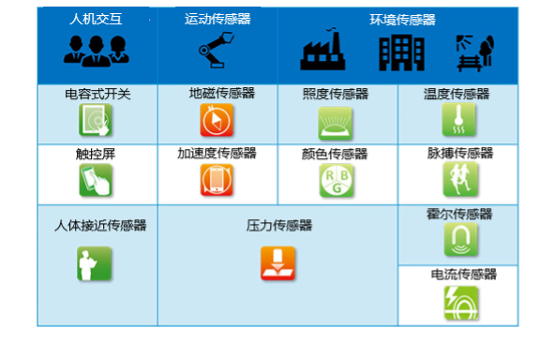
A sensor is essentially a device or apparatus that can “convert physical quantities.” To obtain information for detection and control, it is necessary to convert the state, properties, and physical changes of an object into electrical quantities, using various physical laws for this conversion. Representative physical quantities that sensors detect and convert include temperature, light, color, pressure, magnetic force, and acceleration. Additionally, many sensors are classified as physical sensors and chemical sensors. In recent years, the application of biosensors for detecting organic substances has also become increasingly widespread.
Typical Sensor Examples
The simplest sensors consist solely of sensitive elements. A sensitive element is a component that can convert physical quantities into electrical quantities. To utilize sensitive elements, signal processing circuits capable of accurately capturing small signals and performing digital processing are also required. In recent years, mainstream products have primarily been sensor modules that integrate sensitive elements and signal processing circuits, often simply referred to as “sensors.” Furthermore, it is not uncommon for units with display and communication functions to also be called “sensors,” so in a broad sense, the term encompasses various product forms.
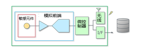
Currently, there are more and more sensors that output digital signals, but the sensitive elements primarily output analog quantities of voltage or current, which are mostly small signals. To utilize these signals, advanced analog and digital processing technologies are required. Sensor technology includes the research and development of sensitive elements used to detect certain phenomena, as well as the design and development of analog front ends for high-precision processing of sensor signals (using amplifiers, filters, AD converters, etc. to adjust the analog signal). This is one of the core technologies in the field of industrial control. In industrial control, information from sensors mainly functions as part of the system, for example, sensor information processed by a computer is used for applications such as closed-loop control of the system.
In the field of the Internet of Things (IoT), due to the wide range of applications for sensors, the requirements for sensors are also diverse. Of course, like in the industrial control field, there are many applications that require advanced sensor technology, such as directly sending relatively simple data like temperature to the cloud and analyzing signs and trends from the accumulated large amounts of data. Such applications, which serve as single data acquisition devices, are becoming increasingly common. Therefore, the current requirements for sensors are not only limited to performance but also include ease of development and design, as well as compactness and lightweight factors.
What is an Accelerometer?
“Acceleration” refers to the change in velocity per unit time, and a sensor that measures this acceleration is called an “accelerometer.” By measuring acceleration, it is possible to detect the degree of changes in an object’s motion, tilt, and vibration.
The units related to acceleration mainly include three:
-
SI unit m/s² (meters per second squared)
-
MKS unit G: standard gravitational acceleration (1G = 9.80665 m/s²)
-
CGS unit Gal: seismic acceleration (100 Gal = 1 m/s²)
Working Principle of Accelerometers
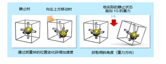
The following diagram illustrates a common detection method for accelerometers. As shown, when the box is moved (for example, moved to the upper left), which means acceleration occurs, the position of the mass connected to the spring will change. By capturing this positional change, acceleration can be inferred.
The right diagram shows the principle of detecting the tilt angle through the position of the mass. When a gravitational force of 1G is applied to a stationary state, if the box tilts, the position of the mass changes. Since the direction of gravity is known, the tilt angle can be detected.
Axes of Accelerometers
Accelerometers have the concept of “axes.” For example, a three-axis accelerometer can detect G forces along the X, Y, and Z axes (directions), which can be simply described as detecting G forces in the up, down, front, back, left, and right directions. The specific number of axes required varies depending on the application. In recent years, three-axis accelerometers that can capture three-dimensional states have become widely used. A three-axis accelerometer is a sensor that integrates three sensors, each used to measure G forces in three different directions.
In the previous diagram used to introduce the working principle, the spring is oriented along the X, Y, and Z directions, thus it is a three-axis sensor. Below is an example of using a three-axis accelerometer for tilt detection. This example should help understand the concept of “axes.”
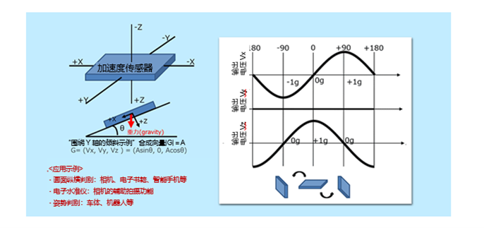
This shows the situation when the Y-axis is fixed horizontally, and the sensor is rotated. At this time, the X and Z axes are changing. The sensor outputs during the changes in the X and Z axes are plotted as voltage values in the curve graph. When rotated from the horizontal state (0 degrees/0g) by 90 degrees, the output Vx of the X-axis becomes +1g. Continuing to rotate to +90 degrees, reaching +180 degrees (horizontal after flipping), the output Vx of the X-axis becomes 0g. Of course, the output Vy of the Y-axis remains 0g. The output Vz of the Z-axis has a phase difference of 90 degrees.
To calculate the tilt angle θ, as shown in the diagram, assuming the resultant vector |G| = A, then G = (Vx, Vy, Vz) = (A sinθ, 0, A cosθ).
Source: Rohm