Detailed Explanation of CRA Parameters for Image Sensors and Lenses and Their Matching Selection
CRA: Chief Ray Angle, which refers to the angle of the chief incident light ray. For both lenses and image sensors, although both have CRA parameters, their actual definitions are significantly different.
CRA Parameters of Lenses
The CRA parameter of a lens is determined by the design of the lens itself, representing the angle distribution pattern of light rays from the lens center to the imaging plane. This means that the chief rays (the rays passing through the entrance pupil center) at various positions of the lens, after passing through the optical system to reach the image plane, form an angle with the normal at the intersection point on the image plane.
As shown in the figure below, the angle of the chief incident light rays at each position of the lens is different, which means that the CRA parameter of the lens is not a fixed value but varies according to the different positions of the lens’s field of view. For example, the figure below shows the chief ray angles corresponding to 14°, 10°, and 0° fields of view for the Double Gauss 28 Degree Field optical system from the ZEMAX lens library.
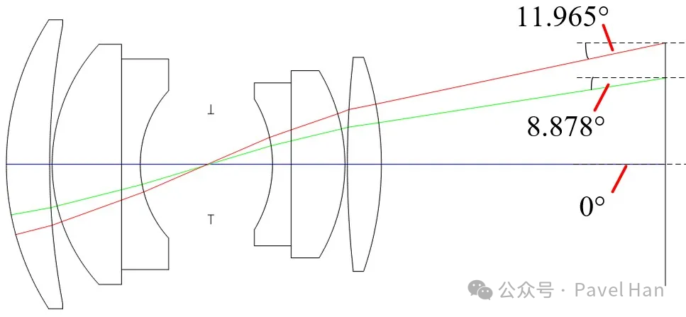
From the above lens ray imaging principle diagram, it can be seen that the larger the lens’s field of view, the larger the corresponding CRA angle. The center position of the lens, which is the 0-degree field of view, can be considered to have a CRA of 0; as one moves towards the edge of the lens, the CRA angle increases. The CRA angle of the lens that we generally refer to usually indicates the CRA angle at the edge of the lens.
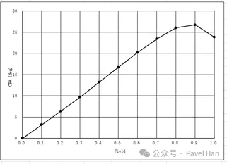
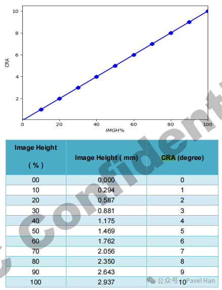
The following figure shows the CRA corresponding to different normalized image heights for a specific lens model. The CRA at the center of the lens is 0, and the chief ray angles at different heights on the lens image plane vary, resulting in a CRA curve that changes with image height.
CRA Parameters of Image Sensors
Compared to the CRA parameters of lenses, the CRA parameters of image sensors are slightly more complex.
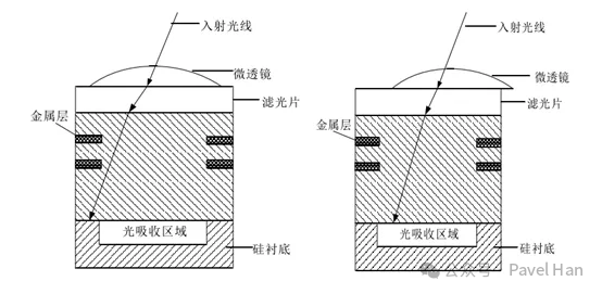
Firstly, each pixel of the image sensor has a small micro lens, which is used to focus as much light as possible entering through the lens onto the underlying photodiode for photoelectric conversion. As seen in the figure below, adding a micro lens above the photodiode can refract more light through this micro lens onto the photosensitive surface, thereby increasing the light flux on the photodiode, which is the main purpose of adding a micro lens.
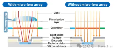
According to the structure of the micro lens above, if the angle of the light entering from the lens is perpendicular to the micro lens (for example, in the center region of the image sensor and lens), then these rays can all enter the light absorption area of the pixel array through the micro lens. However, if the light entering from the lens strikes the micro lens at a certain angle (for example, at the edge of the image sensor and lens), after refraction by the micro lens, these rays will hit the metal layer above the pixel (as shown in the gray area in the figure above), failing to reach the central absorption area. This results in a decrease in light intensity in the light absorption area, leading to reduced sensitivity of the edge pixels and increased optical crosstalk. As shown in the figure below.
The above issue leads to the design of the micro lens shift.
Micro Lens Shift Design
To address the pixel sensitivity issue at the edge of the image sensor (where light from the lens strikes the micro lens at an angle), the micro lens needs to be shifted a certain distance. This allows the light, after refraction, to refocus the light that was lost before the lens was shifted back onto the light absorption area. As shown in the figure below, after shifting the micro lens towards the center by a certain distance, light entering at an angle will be refracted by the micro lens to the central absorption area of that pixel.
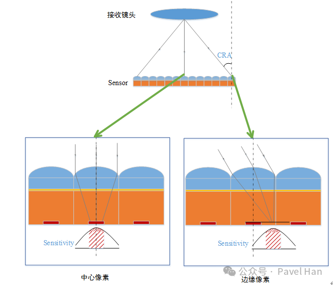
From the optical theory of the lens CRA, it is understood that the angle of the chief incident light rays entering the image sensor’s photosensitive surface is related to the positions of the lens and the sensor’s photosensitive surface. In general optical applications, the optical axis centers of the lens and sensor coincide, so at the center position of the sensor, the chief ray angle from the lens is essentially perpendicular to the micro lens of the central pixel, allowing most of the light to be refracted to the central absorption area.
As one moves outward from the center, the angle of the chief rays entering the lens increases. At this point, the micro lenses of the pixels in the surrounding areas of the sensor can be shifted as described above. The direction and magnitude of the shift should be related to the angle of the chief incident light rays at that position.This is the issue of matching the CRA between the lens and the sensor.
The Sensor’s CRA is Also Related to the Pixel Location
Similarly, for the design of the image sensor, the direction and magnitude of the shift of the micro lens on the sensor pixel should match the angle of the chief rays that it is supposed to receive. This is the CRA parameter required by the sensor. Likewise, with the center of the sensor as the axis, the CRA at the center of the sensor is 0, while the CRA varies at different positions extending outward from the center; the closer to the edge of the sensor, the larger the CRA.
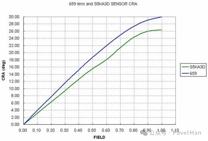
The following is the CRA data for the GC4653, where the CRA at the center position of the sensor is 0, and the CRA at the edge position approaches 10 degrees.Generally, the CRA data we see in the sensor’s datasheet is the maximum CRA angle at the edge position.
CRA Matching Selection for Sensors and Lenses
During the selection process for image sensors and lenses, special attention must be paid to the matching of their CRAs. The ideal situation is for the CRA of the lens and the CRA of the sensor to achieve perfect matching, resulting in the highest light reception efficiency. However, in practical applications, achieving perfect matching is difficult.In this case, it should be ensured that the difference between the lens CRA and the sensor CRA is controlled within 2-3 degrees..
If the CRA of the sensor and the lens do not match, there will be difficult-to-solve issues with the image quality during later adjustments:
- • When Lens CRA > Sensor CRA, the light entering from the lens will exceed the correction capability of the sensor’s micro lens, leading to adjacent pixel crosstalk (Color Shading), specifically manifested as color distortion at the edges of the image.
- • When Lens CRA < Sensor CRA, the light entering from the lens cannot cover the edges of the pixels, resulting in a loss of photosensitive area (Luma Shading), specifically manifested as dark corners in the image.
During actual image IQ adjustments, since Color Shading (color deviation) is more difficult to correct in post-processing through ISP than Luma Shading (uneven brightness), it is recommended to choose a solution where the Lens CRA is slightly less than the Sensor CRA.
Image Issues Due to CRA Mismatch
As mentioned above, when the CRA of the lens and the sensor do not match, some image-related issues will arise. How exactly do these image issues occur?
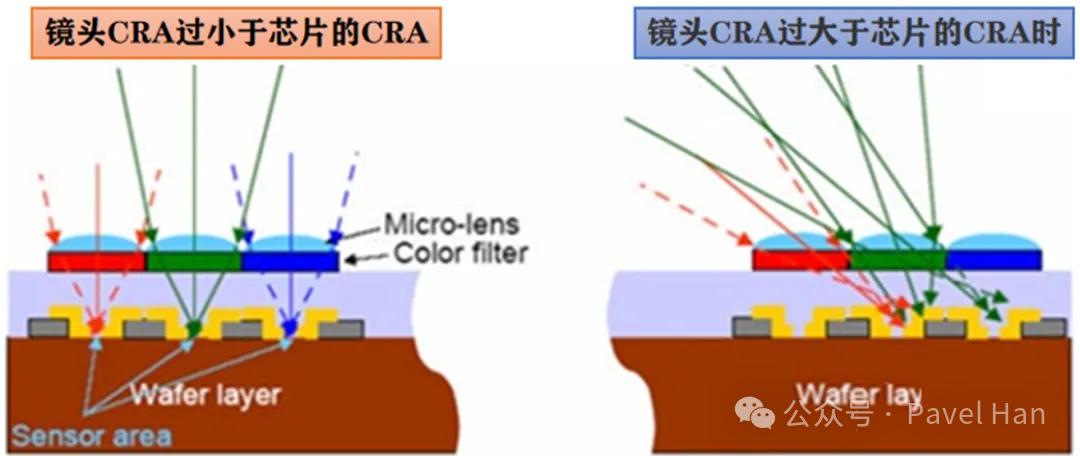
Referring to the figure above, when the CRA of the lens is significantly smaller than that of the sensor, the light entering from the lens to the edge pixel micro lens of the sensor is refracted to the non-sensitive area of the pixel, resulting in insufficient light flux that can be absorbed by the photosensitive area, leading to a darkening of the image edges. This is the issue of Luma Shading.
Conversely, if the CRA of the lens is significantly larger than that of the sensor, the CRA of the light entering the edge pixel of the sensor is too large, causing these rays to refract to neighboring pixels of different colors after passing through the sensor’s edge pixel micro lens, leading to interference between pixels. This is the issue of Color Shading.
References
- • What is CRA?
- • Analysis of the Matching Problem between Lens CRA and Sensor CRA
- • A Brief Discussion on the Design of Detector Micro Lenses