Dedicated to the research and development of digital twin technology
Benefiting humanity through solutions and engineering applications
Source: United Reference
Abstract
The application of digital twin technology in the development and testing of systems and their subsystems has become quite mature. However, its application in the development and testing of autonomous systems is an emerging field. The complexity of autonomous system testing lies in the need to assess the ability of machines to perform specific functions similar to those of humans, including mimicking human structure, perception, intuition, and learning capabilities. Digital twins play a key role in this process, focusing on precise modeling and simulation of the environment rather than simply mimicking human perception. This article describes how the U.S. Army Aberdeen Test Center applied digital twin technology to test the performance of autonomous systems while driving the Palettized Load System (PLS) to verify the capability of autonomous systems to replace human drivers.
Background
The U.S. Army Aberdeen Test Center (ATC), part of the U.S. Army Test and Evaluation Command (ATEC), identified the need for virtual experimentation of autonomous ground vehicles. To this end, the System Integration Laboratory (SIL) was established to run thousands of scenarios on a road simulator using virtual leaders and real-time followers, aided by high-performance computing (HPC) for testing. The establishment of SIL is a mature system integration approach, but its application to autonomous systems presents greater challenges. The integration process requires simulating or emulating the basic functions of autonomous sensors and vehicles. The article will explain how to identify failure areas and environmental conditions in the PLS and leader/follower scenarios. The program requires a human leader and ensures that the following vehicle can autonomously follow within a specified distance or time and can stop when encountering obstacles. This article focuses on testing autonomous ground vehicles and fleets, excluding armed unmanned ground vehicles or unmanned aerial vehicles, and emphasizes using digital engineering tools for testing rather than development stages.
Objective
This article aims to introduce the testing procedures and tools for autonomous ground vehicles and clarify the methodologies adopted by ATEC. The goal is to ensure that future autonomous systems are ready for field testing and to comprehensively demonstrate the capabilities of autonomous systems through efficient field testing scenarios. The Aberdeen Test Center and ATEC only received the autonomous systems a few weeks before soldier validation, and ATEC was also responsible for writing safety documents to support demonstration validation and the safety confirmation of equipped troops. Due to time and budget constraints, a complete list of scenarios could not be executed to review these systems, so great care must be taken when drafting safety release documents.
Methodology
The Autonomous System Testing Capability (ASTC) project was initiated in May 2020 to develop tools that meet the aforementioned needs. This project, funded by the U.S. Department of Defense Test Resource Management Center, is approximately $16 million and is part of the Central Test and Evaluation Investment Program. The project lasted two years and was completed in December 2022. ASTC uses virtual environments to test autonomous software decision-making capabilities, creating digital visuals and mechanical twins of terrain, specific maneuver performance vehicles, sensors, and the integrated autonomous software under test. A 3D computer graphics game engine called Unreal Engine is used to integrate all these components.
System Integration Laboratory (SIL) Development
The System Integration Laboratory (SIL) is an effective method for validating that the code runs as planned and that the defined subsystems communicate and share data according to the designed interfaces. It consists of software under development and hardware replicas intended for vehicles. The software is verified against design standards through simulation or stimulation, for example, by simulating moving components responding to autonomous software commands and sending the planned corresponding responses back to the autonomous software.
Autonomy
Autonomy or artificial intelligence/machine learning can perform a range of tasks from simple to complex. In this article, we take the PLS follower driving as an example, which is part of a military convoy with specific tasks and gap distances. These tasks are based on a complex set of military tasks and sub-tasks derived from the overall military mission description.
When researching how autonomous software works, the first step is to analyze its inputs and outputs. The following vehicle operates based on commands and specific information from the lead vehicle, such as speed and acceleration at specific locations. Therefore, the System Integration Laboratory should include information from at least two vehicles in testing, or information from the lead vehicle. This data is transmitted through standard computer communication patterns, triggering a response from the autonomous software. Section 3.5 details how to simulate actual radio communication performance by modifying the data sent from the leader to the follower and testing responses to potential error conditions.
Once the autonomous software receives the correct commands, it retrieves data from onboard sensors (such as GPS) to determine whether the distance is suitable for executing movement commands. It also receives data from LiDAR sensors to ensure that moving in the specified direction is safe. If there are no obstacles, the autonomous software sends commands to the motion simulator to simulate vehicle movement. The new position information is provided by the GPS simulator and updates the follower’s location. This change in position reflects the new commands made by the autonomous software based on the current location and data provided by the LiDAR subsystem. Sections 3.6 and 3.8 describe how to actually modify LiDAR data to test responses to potential error conditions.
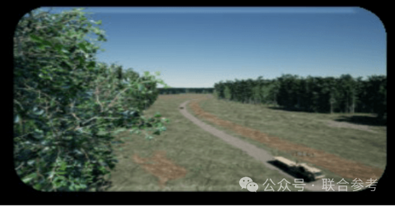
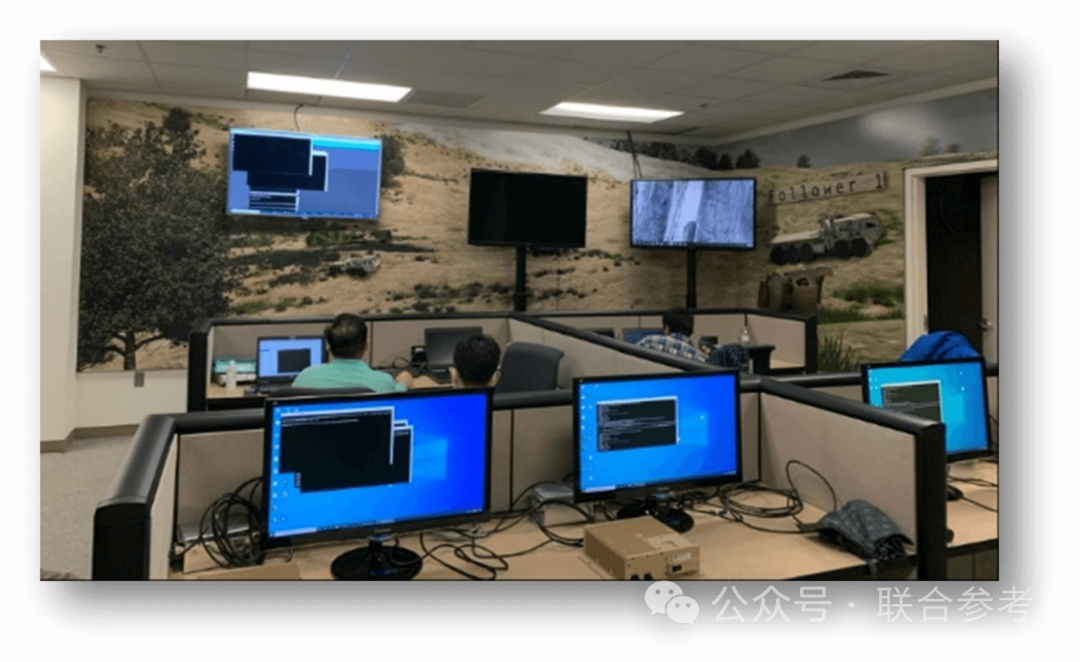
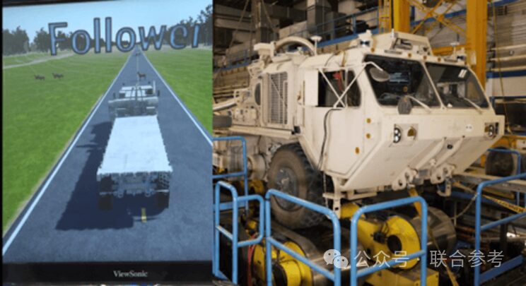
In the “Leader/Follower” model, the “autonomous under test” is referred to as the “Autonomous Kit (A-Kit).” There is also a “By-Wire Kit (B-Kit),” which receives requests from the A-Kit and sends necessary signals to the actual vehicle to move according to the A-Kit’s commands. The B-Kit is simulated in SIL, as creating a detailed real-time vehicle system model is both complex and costly. By simulating, the A-Kit can operate as usual, allowing for thorough testing in a laboratory environment. B-Kit testing is completed through hardware-in-the-loop simulators, which are used for air traffic control road simulators for military vehicles. This simulator simulates vehicle motion, including turning, but does not physically move. Using this simulator, automated convoy tests can be conducted with a real vehicle. The digitized virtual leader can interact with both real followers and other virtual followers. Although the real follower believes it is following the lead vehicle, it is actually simulating on the simulator. The following images demonstrate this capability: in December 2021, a driver operated the virtual leader on the ATC Perryman test track and sent location signals to the real follower on the road simulator. These images also show that after interacting with a virtual deer, the follower was able to stop in a timely manner. This was achieved by shutting off the sensors on the real follower and providing feedback from the sensors in the virtual scene instead.
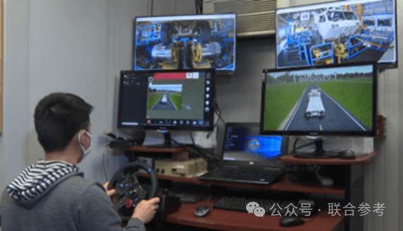
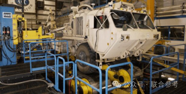
Figure 4: Reference material concerning the road simulator
Simulation/Stimulation
Simulation/stimulation refers to modeling that affects a system or subsystem over time. It provides inputs or responses to software systems or subsystems to assist in functional testing. In A-Kit testing, simulation and stimulation are used together. Key performance inputs, such as LiDAR, whose simulation is crucial for A-Kit’s response, should accurately simulate its performance, including variations affected by the operating environment. LiDAR is highly sensitive to environmental conditions such as rain, snow, fog, and dust. Section 3.8 discusses how weather can actually affect LiDAR simulation and methods used for testing and validating A-Kit software functions. Stimulation is used to replicate some necessary subsystem functions, keep the A-Kit operating normally, and simulate subsystems for detailed performance testing. The navigation box is a stimulated subsystem in the leader/follower system that is responsible for vehicle positioning. Vehicle positioning relies on GPS, inertial motion units (IMU), wheel encoders, and terrain registration inputs. The calculated position, distance to the target, and information from the leader help the A-Kit decide what directional and speed suggestions to provide to the B-Kit.
Fault Injection
Fault injection is a testing method used to evaluate how unmanned vehicles respond to abnormal simulated or stimulated input data to ensure safety. This is achieved by injecting faults into specific subsystems such as A-Kit, B-Kit, or the navigation system. For example, vehicle faults may involve the engine, power system, suspension system, power transmission system, steering, braking, or wheels and tires. Particularly interesting are air brake pressure faults, as they may affect the distance between the leader and follower. This helps analyze the A-Kit’s response when losing air brake pressure and describes the abnormal interval distance rules that arise in specific situations, such as when vehicles traverse hilly terrain.
Supporting both time-based and event-based fault injections is crucial. Time-based fault injection provides testers with better control levels and ensures consistency and repeatability. Event-based fault injection supports more dynamic injections. Other beneficial fault injections include degrading sensor data quality, such as LiDAR data, or degrading communication quality between vehicles and external systems. These two scenarios will be further discussed in Sections 3.5 and 3.6.
Communication System Degradation Fault Injection
To effectively guard against potential degradation issues that may arise during communication tests, the SIL system allows us to monitor how radio performance affects data transmission between the “leader” and “follower” vehicles. This process can be achieved by sending specific messages to communication applications via fault servers, i.e., fault injection. These messages contain network traffic control instructions, which, when executed, manipulate the network data through various means such as packet loss, duplication, delay, or bandwidth changes.
As mentioned, by simulating specific inputs, we can observe and verify the vehicle’s response to these inputs, thus confirming whether the code operates as expected. For example, if we intentionally cause a 100% packet loss, we will observe that the vehicle pauses operation due to not receiving radio signals. In this way, we can precisely control radio performance testing and respond to various fault scenarios that may occur in reality.
LiDAR Fuzzing Fault Injection
In terms of LiDAR fuzzing fault injection, to simulate the degradation of LiDAR (LiDAR) signals in real-world environments, we employ LiDAR fuzzing technology. This technology is implemented at the network interface level by intercepting and modifying incoming LiDAR data streams before sending them to the original target, thereby simulating various faults. The LiDAR fuzzing service can control fault modes and communicate with the fault service described in Section 3.7 to report and adjust statuses. Through these real-time modifications, we can observe how the automatic controller is disturbed under adverse environmental conditions.
Since LiDAR fuzzing is conducted in real-time, it is necessary to use tools such as Wireshark to record network traffic or VeloView to visually observe output results. Even very low proportions of change can significantly affect LiDAR performance.
Fault Management
To effectively manage various fault services, it is recommended to create a centralized fault management program. This way, users can manage all fault injections through a unified interface. The ASTC fault server can remotely create faults and send them to the corresponding services.
The ASTC fault server is accessed via a network server and can simultaneously send fault information to specific vehicles or an entire fleet. Any computer connected to the network and running NodeJS can run this program, allowing for rapid deployment without modifying each service. External fault management servers can also arrange faults, manage activation statuses, and store all fault information. Keeping microservices minimal enhances customizability and reduces the burden on A-Kit computing capabilities from each microservice.
The ASTC fault server can dynamically create faults and send them in batches to vehicles via a website or JSON file. Each fault service receives the faults injected by the server and tracks and saves them using UUID identifiers.
LiDAR Simulation Weather Effects
The ASTC SIL uses the commercial game engine Unreal Engine. Performance issues of LiDAR, particularly concerning weather conditions involving particles, are not well modeled in the virtual engine. This often means that the performance of LiDAR models using the game engine under weather conditions is superior to that in the real world. Since LiDAR is a key input lever for the A-Kit, we developed a virtual autonomous navigation environment: Environmental Sensor Engine (VANE: ESE).
VANE uses the Phong model to simulate the interaction of radiative energy (light) with the environment. The Phong model describes how much energy is reflected when emitted energy strikes a surface at a given angle and given reflectivity. In the case of the LiDAR sensor in VANE: ESE, the Phong model implements tracking the laser beam emitted from the emitter along a vector to a surface. The surface is described with a reflectivity index encoded into texture mapping.
Specialized LiDAR sensor modeling in VANE: ESE first models according to specifications declared by the manufacturer. Then, the model is verified to operate according to the descriptions in the manufacturer’s data sheet specifications. LiDAR specifications typically include wavelength, field of view, frame/rotation rate with angular resolution, minimum/maximum detection range, distance accuracy, sampling rate, and beam description (divergence, shape). The model is then validated based on laboratory test results. Finally, the LiDAR sensor is placed in initially clear field conditions and then subjected to rain, fog, snowfall, and dust conditions for comparison and adjustment with the VANE: ESE sensor model. After applying firmware updates from the manufacturer, the model may need to be readjusted.
Additionally, LiDAR manufacturers typically do not describe sensor performance degradation rates for rain, visibility distances for fog, snowfall rates, or various dust concentrations. Therefore, it is necessary to consult literature and conduct field tests to describe how various weather or environmental conditions degrade sensor performance. Again referencing the Phong model, when light is emitted, it passes through a medium before reaching a surface or target. When light passes through a medium, if the beam encounters particles that can absorb or scatter part of the beam’s energy, energy is lost. For example, raindrops, fog aerosols, snowflakes, and dust particles scatter light beam energy based on particle concentration and the size of the particles relative to the laser wavelength.
Conclusion
In summary, the construction of the aforementioned functions is crucial for testing. They enable testing units to begin testing early in the procurement cycle, thus saving resources later on. Although field testing is still necessary, the application of these tools can significantly reduce the number of required tests. During field testing, we can conduct risk assessments and develop corresponding procedures to ensure that unmanned vehicles are tested in a safe and effective environment. This not only reduces real-time testing but also allows for scenarios that cannot be tested from a resource perspective. This will allow programs to reduce real-time testing while gaining more information. We studied previous test systems to determine whether the methods listed above were adopted, and a typical test scenario could run in 2.5 hours. These will not replace field tests but will discover information, requiring 8-10 weeks of field testing track. This process can be completed at one-fifth the cost while saving 3200 gallons of fuel.

Digital Twin Business Architecture
Follow “Anshi Asia Pacific” for exciting updates