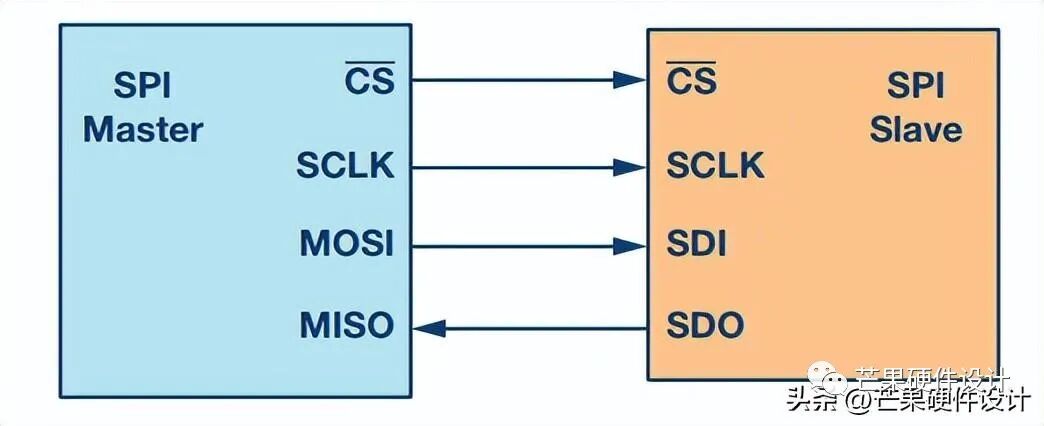
SPI (Serial Peripheral Interface) is one of the most widely used interfaces between microcontrollers and peripheral ICs (such as sensors, ADCs, DACs, shift registers, SRAM, etc.). SPI is a synchronous, serial interface. Data from the master or slave is synchronized on the rising or falling edge of the clock. A common 4-wire interface is shown below:

SCK: Clock
MOSI: Master Out, Slave In. MOSI sends data from the master to the slave, while MISO sends data from the slave to the master.
MISO: Master In, Slave Out. MOSI sends data from the master to the slave, while MISO sends data from the slave to the master.
SS: Slave Select. The slave select signal from the master is used to select the slave. This is usually an active-low signal, which disconnects the slave from the SPI bus when pulled high. When using multiple slaves, the master needs to provide a separate slave select signal for each slave.
The device that generates the clock signal is called the master. The data transmitted between the master and the slave is synchronized with the clock generated by the master. Compared to the IIC interface introduced in the previous article, SPI devices support higher clock frequencies (commonly reaching Mbps, which is much faster than IIC).
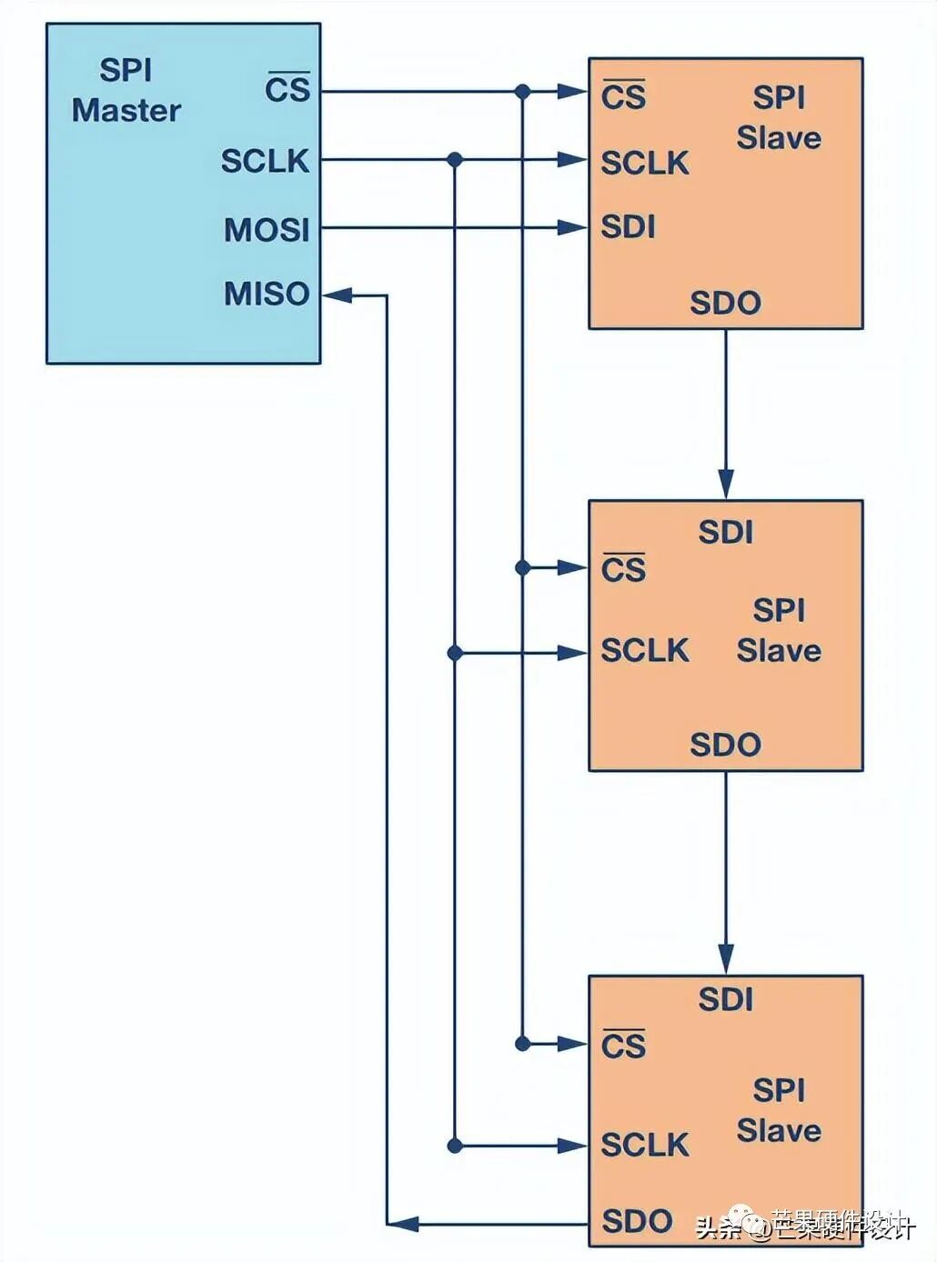
SPI Topology:
Figure a shows a common hardware topology with one slave, while figure b shows a daisy chain topology used when there are multiple slaves. From the figures, it can be seen that CLK, MOSI, and MISO can be shared, while the CS signal needs to be connected to different slaves to distinguish between different components. (This is different from IIC, which distinguishes between devices using addresses).
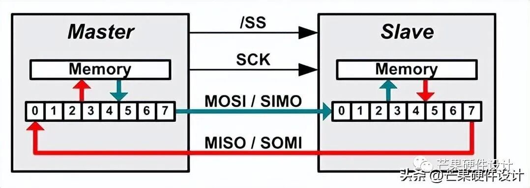
SPI Data Transmission:
The SPI communication master must send a clock signal and select the slave by enabling the CS signal. The chip select is usually an active-low signal. Therefore, the master must send a logic 0 on this signal to select the slave. SPI is a full-duplex interface, allowing the master and slave to send data simultaneously through the MOSI and MISO lines. During SPI communication, data transmission (serially shifting out to the MOSI/SDO line) and reception (sampling or reading data on the MISO/SDI line) occur simultaneously. The serial clock edge synchronizes the shifting and sampling of data. The SPI interface allows users to flexibly choose the rising or falling edge of the clock to sample and/or shift data. The following diagram shows the exchange of SPI data:
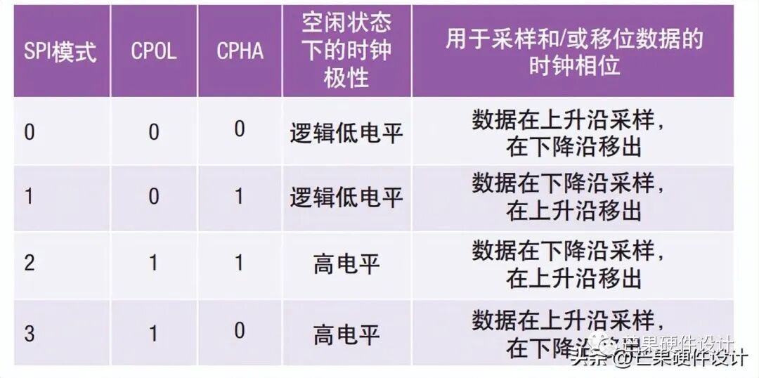
Clock Polarity and Phase of SPI:
In SPI, the master can choose the clock polarity and clock phase. The CPOL bit sets the polarity of the clock signal during idle state. The idle state refers to the period when CS is high at the start of transmission and transitions to low, as well as when CS is low at the end of transmission and transitions to high. The CPHA bit selects the clock phase: depending on the state of the CPHA bit, data is sampled and/or shifted on the rising or falling edge of the clock. The master must select the clock polarity and clock phase according to the requirements of the slave. Based on the selections of CPOL and CPHA bits, four SPI modes are available.