 Methods for Testing the CAN Bus① Before checking the data bus system, ensure that all electronic control units (ECUs) connected to the data bus are free of functional faults. A functional fault refers to a failure that does not directly affect the data bus system but impacts the functional flow of a specific system. For example, if a sensor is damaged, the result is that the transmitter signal cannot be transmitted through the data bus. This type of functional fault indirectly affects the data bus system and can hinder communication between ECUs that require the sensor signal. If a functional fault exists, it should be resolved first. Record the fault and clear all fault codes from the ECUs.② After eliminating all functional faults, if data transmission between ECUs is still abnormal, the data bus system needs to be checked.When checking for faults in the data bus system, the following two scenarios must be distinguished:■ Testing a two-wire data bus system composed of 2 ECUs.■ Testing a two-wire data bus system composed of 3 or more ECUs.③ If no cause for hardware damage can be found on the data bus, check if a specific ECU is causing the fault.Disconnect all ECUs transmitting data via the CAN bus, turn off the ignition switch, and connect one of the ECUs. For example, for Volkswagen system models, connect the diagnostic tool, turn on the ignition switch, and clear the fault codes of the newly connected ECU. Use function 06 to end the output, turn off and then turn on the ignition switch, and after 10 seconds, use the diagnostic tool to read the contents of the fault memory of the newly connected ECU. If “hardware damage” is displayed, replace the newly connected ECU; if “hardware damage” is not displayed, connect the next ECU and repeat the above process.Common Faults and Causes of the CAN Bus(1) Common Faults of the CAN BusIn the CAN bus ECUs, there may be records of two types of bus faults: CAN communication faults and CAN bus line faults.① CAN Communication FaultsCommunication faults can occur in the following two situations:■ Open circuit in the ECU.■ Damaged ECU.② CAN Bus Line FaultsCAN bus line faults can occur in several situations:■ Short circuit in the CAN bus wire.■ Open circuit in one of the CAN bus wires.■ Grounding of the CAN bus wire.■ Open circuit between CAN bus wires.■ Cross connection between CAN-Low and CAN-High wires.■ Short circuit of the CAN-Low wire to the positive terminal of the battery.■ Short circuit of the CAN-High wire to the positive terminal of the battery.■ Short circuit of the CAN-Low wire to the negative terminal of the battery.■ Short circuit of the CAN-High wire to the negative terminal of the battery.(2) Causes of CAN Bus FaultsThe causes of communication faults in the CAN bus are as follows:① Open circuit or short circuit in the CAN-Low or CAN-High communication lines.② Damage to the connector, such as contact damage, dirt, or corrosion.③ Voltage faults in the vehicle’s power supply system, such as those caused by a damaged ignition coil or grounding connection.④ Faults in the communication components of a specific ECU.⑤ Power supply faults in a specific ECU. When the battery is nearly depleted, the battery voltage may gradually drop, potentially leading to fault code storage, as not all ECUs shut down simultaneously due to voltage drop.Short circuits to the positive terminal and grounding, as well as short circuits between wires on the CAN bus, will not damage the ECUs, but in the most severe cases, may cause the bus system to fail. The bus system in the vehicle can experience not only open or short circuit faults, but also when moisture enters the connectors in the bus system, contact resistance may occur between the ground, positive terminal, and CAN bus wires, causing the bus system to operate abnormally.Multimeter Testing Methods for the CAN BusThe CAN bus can be tested for voltage signals using a digital multimeter to roughly determine if there are faults in the signal transmission of the data bus. The testing method is shown in the figure below.
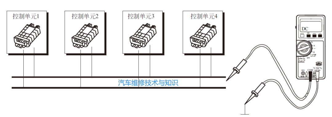 ▲ Multimeter Testing of the CAN BusWhen measuring frequency signals with a digital multimeter, the multimeter has the characteristics of segmented sampling and effective value calculation, therefore, the displayed value of the digital multimeter can only reflect the main signal voltage value of the measured signal and cannot display every detail of the measured signal. Thus, when measuring the signal voltage of the CAN bus with a digital multimeter, the displayed value of the multimeter corresponds to the main signal voltage value of the CAN bus.(1) Measuring the Power CAN Bus with a MultimeterThe CAN-High signal voltage when the bus is idle is approximately2.5V, and when there is signal transmission on the bus, the voltage fluctuates between 2.5V and 3.5V, so the main voltage of CAN-High should be 2.5V, thus the measurement value with the multimeter should be 2.5V to 3.5V, greater than 2.5V but close to 2.5V.Similarly, the CAN-Low signal voltage when the bus is idle is approximately2.5V, and when there is signal transmission on the bus, the voltage fluctuates between 1.5V and 2.5V, so the main voltage of CAN-Low should be 2.5V, thus the measurement value with the multimeter should be 1.5V to 2.5V, less than 2.5V but close to 2.5V.(2) Measuring the Comfort CAN Bus with a MultimeterThe Comfort CAN signal voltage when the bus is idle is approximately0, and when there is signal transmission on the bus, the voltage fluctuates between 0V and 5V, so the main voltage of CAN-High should be 0, thus the measurement value with the multimeter should be around 0.35V.Similarly, the CAN-Low signal voltage when the bus is idle is approximately5V, and when there is signal transmission on the bus, the voltage fluctuates between 0V and 5V, so the main voltage of CAN-Low should be 5V, thus the measurement value with the multimeter should be around 4.65V.(3) Testing the Termination Resistors of the CAN BusTo measure the total resistance of the two termination resistors, the VAS5051 diagnostic tool can be used in multimeter mode, as shown in the figure below.
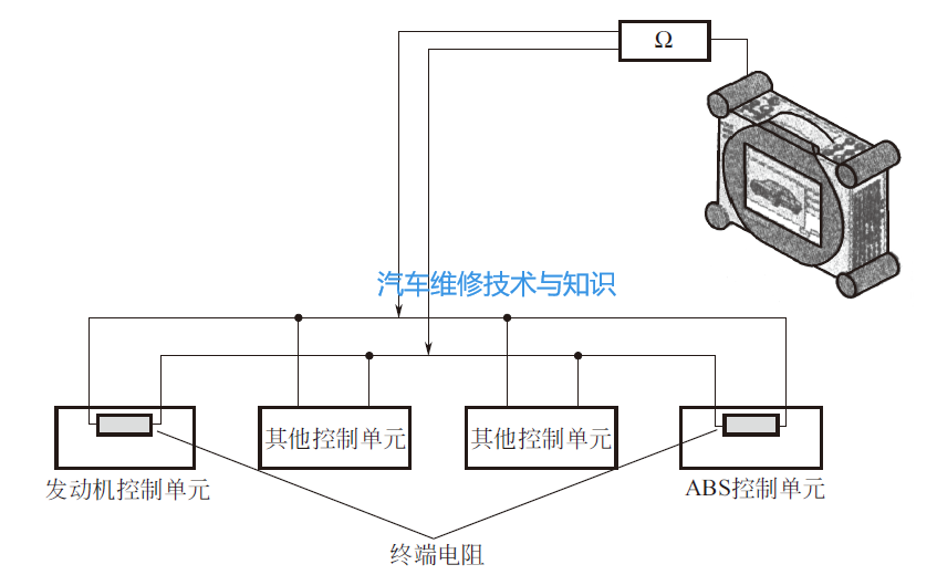 ▲ Measuring the Total Resistance of Two Termination ResistorsThe steps for measuring the termination resistors are as follows:① Disconnect the wires (cables) from the positive and negative terminals of the battery.② Wait for about 5 minutes until all capacitors are fully discharged.③ Connect the VAS5051 diagnostic tool, activate the multimeter function, connect the measurement leads, measure the total resistance of the termination resistors, and record the results.④ Disconnect the connector of an ECU with a termination resistor (e.g., the engine ECU) and observe whether the total resistance of the termination resistors changes.⑤ Reconnect the connector of the first ECU (with a termination resistor, such as the engine ECU), then disconnect the connector of the second ECU (with a termination resistor, such as the ABS ECU), and observe whether the total resistance of the termination resistors changes.⑥ Analyze the measurement results.The termination resistors set within the ECUs are not fixed resistance values; they are composed of multiple measured resistors combined together. For example, in a 1.9TDI model with a pump nozzle unit, the engine ECU is set to a 66Ω termination resistor. The termination resistor is designed according to the model, and the total resistance value depends on the vehicle’s bus structure.After measuring the total resistance value, it is also necessary to disconnect the connector of an ECU with a termination resistor and perform two measurements of individual resistances. If the resistance value changes after the ECU is removed, it indicates that both resistances are normal.The termination resistors installed on the drive CAN bus can be measured with a multimeter, but those installed on the comfort CAN bus and information CAN bus cannot be measured with a multimeter.For example, taking the Audi A2 1.4 model as an example, analyze the total resistance of its drive CAN bus. The two ECUs with termination resistors are connected through the CAN bus harness, and the two termination resistors are in parallel on the bus. The measured result shows that each termination resistor has a resistance of about 120Ω, and the total resistance is about 60Ω. Based on this measurement data, it can be concluded that the termination resistors of the drive CAN bus are normal.It is important to note that the resistance value of a single termination resistor may not necessarily be around 120Ω; its specific value varies depending on the bus structure.Additionally, when analyzing the individual resistance of the drive CAN bus in the Audi A2 1.4 model, after measuring the total resistance, disconnect the connector of an ECU with a termination resistor, and then measure again. At this point, the resistance value displayed on the screen should change (this measures the termination resistance value of one ECU, which is the actual measured value of the individual termination resistor of the drive CAN bus).If the resistance value does not change after disconnecting the connector of an ECU with a termination resistor, it indicates that there is a problem in the system. The termination resistor of the removed ECU may be damaged, or there may be an open circuit in the CAN bus. If the displayed resistance value becomes infinite after removing the ECU, then either the termination resistor of the ECU that was not removed is damaged, or there is an open circuit fault in the CAN bus wire leading to that ECU.This content is sourced from: “Vehicle Network System Repair and Case Studies”, edited by Wu Wenlin, published in June 2016 Related Articles more
-
Steps, Methods, and Precautions for Diagnosing CAN Bus System Faults
-
Common Repair Methods for the CAN Bus (Essential Knowledge)
-
Common Faults and Diagnostic Methods for FlexRay Bus Systems
-
Types of Automotive Buses, Fault Characteristics & Case Analysis
-
[Typical Case] Automotive Bus Fault Repair Cases (3 cases)
-
Analysis of Air Conditioning Cooling Fault Cases Caused by Automotive Buses (2 cases)
-
117-page PPT Explaining Automotive CAN Data Bus, Not to be Missed!
-
Key Components of the CAN Bus System and Solutions to Technical Faults
 Click below“Read the original text”Let’s recharge together!
 I appreciate your likes and shares!