Welcome FPGA engineers to join the official WeChat technical group.
Clickthe blue textto follow us at FPGA Home – the best and largest pure FPGA engineer community in China.
The Xilinx 7 Series FPGAs are equipped with an ADC called XADC.
This XADC contains two 1 Mbps ADCs that can convert analog signals into digital signals for use within the FPGA.
The XADC can directly obtain the chip temperature and several supply voltages of the FPGA (the 7 series does not include VCCO) to monitor the internal status of the FPGA. It also provides 17 pairs of differential pins, including one pair of dedicated analog differential inputs and 16 pairs of multiplexed analog differential inputs, which can be used as ordinary User I/O when not in use.
For specific structures, functions, and meanings of various parameters of the XADC, please refer to the relevant documentation. A few points need to be noted.
1. The reference voltage setting will affect the error range and the calculation formula of the sampling value.
2. The analog differential input has requirements for the amplitude of the analog signal, which needs some degree of conversion by external analog circuits.
For more information about reference voltage and the implementation of external analog circuits, please refer to the design document UG480.
https://www.xilinx.com/support/documentation/user_guides/ug480_7Series_XADC.pdf
Assuming we need to use the XADC to obtain information from several analog signals, how should we operate? Below is an explanation of a preferred setup.
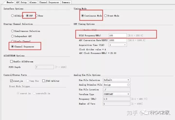
Note the following points in the red box:
1. Use the DRP port to obtain digital signals, as this seems to be simpler to control.
2. Use continuous sampling mode, where the ADC continuously operates in data acquisition mode and can output after sampling.
3. Use Channel Sequencer mode, as there are only two XADCs but too many data to sample, so let the XADC sample sequentially.
4. Set the clock frequency for the DRP port.
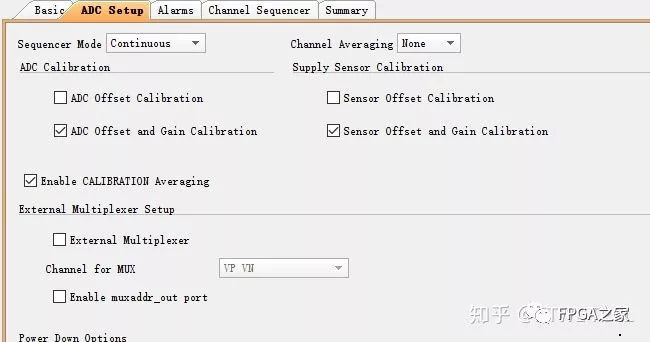
The second page of IP settings mainly involves setting Calibration, averaging, and external MUX. These can be temporarily skipped; once familiar with using the XADC, you can delve deeper.
The third page sets alarm parameters, which can be left as is. If needed, you can set them for convenience.
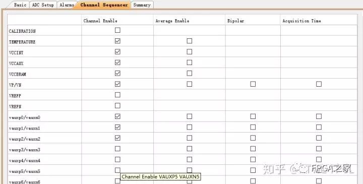
The fourth page sets the channels to be used; here, we choose temperature and three supply voltages, and select one dedicated analog input channel and the first three multiplexed analog input channels.
The last page is the Summary, where you can check if there are any issues with the settings and see if anything needs to be adjusted.
At this point, the basic multi-channel data acquisition setup for the XADC is complete. For areas not discussed in detail in the settings, you can research them once you become proficient and find the most suitable usage mode.
Below is how to use the generated IP. Since we are using the DRP port to read data, we need to design a DRP read/write controller. However, since the XADC itself provides some signals, this design is actually very simple.
.di_in(di_in),
.daddr_in(daddr_in),
.den_in(den_in),
.dwe_in(dwe_in),
.drdy_out(drdy_out),
.do_out(do_out),
.dclk_in(dclk_in),
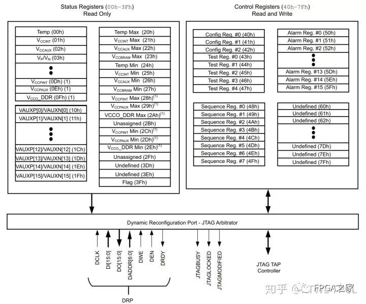
First, let’s clarify the DRP port, which has seven main signals. Since we are only reading data, there is no need to use the input part.
.di_in     (16'b0),
.dwe_in    (1'b0),
The clock signal should connect to the clock used by the DRP, and note that the frequency needs to match the settings in the XADC IP.
.daddr_in  ({2'b00,CHANNEL_OUT}),
.den_in    (EOC_OUT),
.do_out    (DO_OUT),
.drdy_out   (DRDY_OUT),

.eoc_out   (EOC_OUT),
.channel_out (CHANNEL_OUT),
The remaining four DRP ports consist of two outputs and two inputs. The two outputs are directly brought out, where do_out is the final required data. This port is 16 bits, and only the high 12 bits should be taken (corresponding to the 12 bits claimed in the XADC).
In the XADC’s IP port, there are also two named eoc_out and channel_out. Connect eoc_out to the den_in port of the DRP port, meaning that when one of the multi-sampling channels completes sampling, it will trigger the DRP port operation to start reading data. The channel_out should be padded with two bits and sent to daddr_in as the address signal for the DRP port operation. This completes the read/write operation of the DRP.
However, the output data will periodically change between several port data. Therefore, it is common to add a filtering setup at the backend, where the specific behavior is that when drdy_out, which indicates the completion of DRP operation, goes high, the value of channel_out is used to determine which channel it is.
always @(posedge clk)begin
    if(DRDY_OUT == 1'b1 && CHANNEL_OUT ==5'd0)begin
        Temperature <= DO_OUT[15:4]     ;
    end else begin
        Temperature <= Temperature      ;
    end
end
For the specific address of each sampling channel, please refer to the manual.
As for the analog differential input pins, they should be directly connected to the corresponding pins at the top level. Note that the Vivado tool may require level constraints for the multiplexed analog pins, selecting the appropriate lvcmos based on the VCCO voltage value, for example, selecting lvcmos18 for a VCCO of 1.8V.
This way, the corresponding analog sampling data can be obtained. Since the analog signal changes that need to be detected are relatively slow in most cases, using the XADC is sufficient for detection.
There are also issues related to the use of XADC with the MIG IP. MIG is the Memory Interface IP, which is the IP for DDR3 and similar DDR memory. Due to the generally high rate of such interfaces, temperature information is needed for some correction. The configuration of the MIG IP will default to enable the XADC.
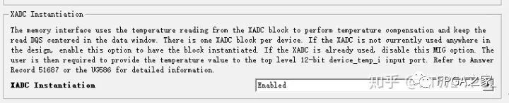
At this point, the XADC only needs to provide temperature information. When more information is needed, the XADC needs to be configured independently, which will generate two XADCs in the project; or if two MIG IPs are instantiated, each will require an XADC. Since there is only one XADC module in the hardware, if multiple XADC modules are needed in the project, the tool will prompt an error.
The solution is straightforward: remove the XADC from the MIG IP, then independently instantiate the XADC IP in the design. After obtaining the temperature information as described above, send it to the MIG. After removing the XADC from the MIG IP, a temperature port will be generated to receive the data. This way, there will be no conflict.
Another very convenient way to obtain temperature information is to use the Hardware Manager. By opening the XADC in the Hardware Manager, you can see the temperature information.
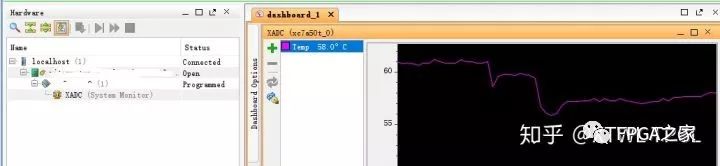
In fact, all channel data from the XADC can be obtained via this method.
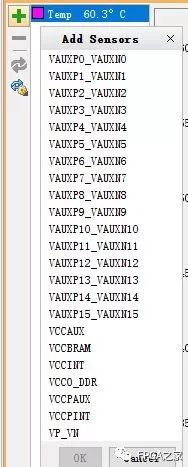
For more usage details, please refer to the UG480 document.

Welcome communication engineers and FPGA engineers to follow our public account.

National Largest FPGA WeChat Technical Group
Welcome everyone to join the national FPGA WeChat technical group, which has tens of thousands of engineers, a group of engineers who love technology, where FPGA engineers help each other and share knowledge, creating a strong technical atmosphere!Hurry up and invite your friends to join!!

Press and hold to join the national FPGA technical group.
FPGA Home Component City
Advantageous component services, please contact the group owner via the QR code: Jin Juan Email: [email protected] Welcome to recommend to procurement.
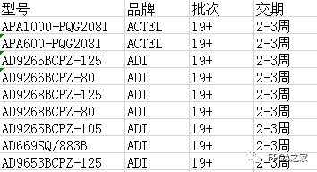
Advantageous ordering for ACTEL and AD (operating the full series):
Advantageous stock or ordering for XILINX and ALTERA (operating the full series):
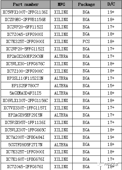
(The above components are part of the models; for more models, please consult the group owner Jin Juan)
Service philosophy: FPGA Home Component City aims to facilitate engineers to quickly and conveniently purchase components. After years of dedicated service, our customer service is spread across major listed companies, military research units, and small and medium enterprises. Our greatest advantage is emphasizing a service-first philosophy, ensuring fast delivery and competitive prices!
Direct brands: Xilinx ALTERA ADI TI NXP ST E2V, and over a hundred other component brands, especially skilled in dealing with components subject to embargo from the US to China.We welcome engineer friends to recommend us to procurement or consult us directly!We will continue to provide the best service in the industry!

Official gratitude to the FPGA technical group brands: Xilinx, Intel (Altera), Microsemi (Actel), Lattice, Vantis, Quicklogic, Lucent, etc.