I/Q Principles and Advantages
For those in communication, optical communication, and RF fields, it is known that in signal processing, the input signal needs to be divided into two paths (I and Q), also known as quadrature modulation signals. Typically, RF signals require shifting low-frequency baseband signals to high-frequency carrier signals for transmission, traditionally achieved through a multiplier that multiplies the signal with the carrier to realize frequency spectrum shifting.
cos(a)*cos(b)=1/2[cos(a+b)-cos(a-b)]
However, this method introduces two additional signal frequencies. Generally, the purer the signal, the better, which plays a decisive role in subsequent interpolation, filtering, and demodulation. Moreover, during the filtering process, it is challenging to filter out the other frequency, unnecessarily increasing the bandwidth and consuming valuable resources. This is why I/Q quadrature modulation technology has flourished in the communication field.
Cos(a-b)=cos(a)*cos(b)+sin(a)*sin(b)
Additionally, the I/Q signal paths can reduce the sampling rate, facilitating the representation of signals in complex signal form (z=a+bi), lowering the sampling rate for each branch, reducing the requirements for ADC, saving development and product costs, and effectively preserving the phase information of the original signal.
Keep it up!
Generating I/Q Signals Using IP Cores in FPGA
Quartus provides an IP core called DDIO IP, which can be used to split the data from high-speed ADC into I/Q signals. This method is generally more convenient and efficient than generating I/Q data through data truncation during processing.
DDIO IP Core (Double Data Rate IO)
DDIO (Double Data Rate IO) implements DDR registers in logic elements (LE). In this program, DDIO_IN is used to create a DDR input interface, where the IP will receive data on both the rising and falling edges of the reference clock, achieving a 2x clock rate for data latching.
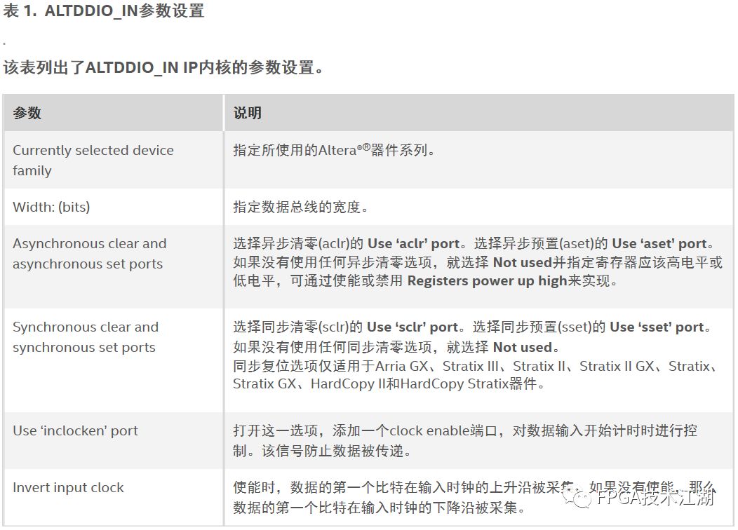
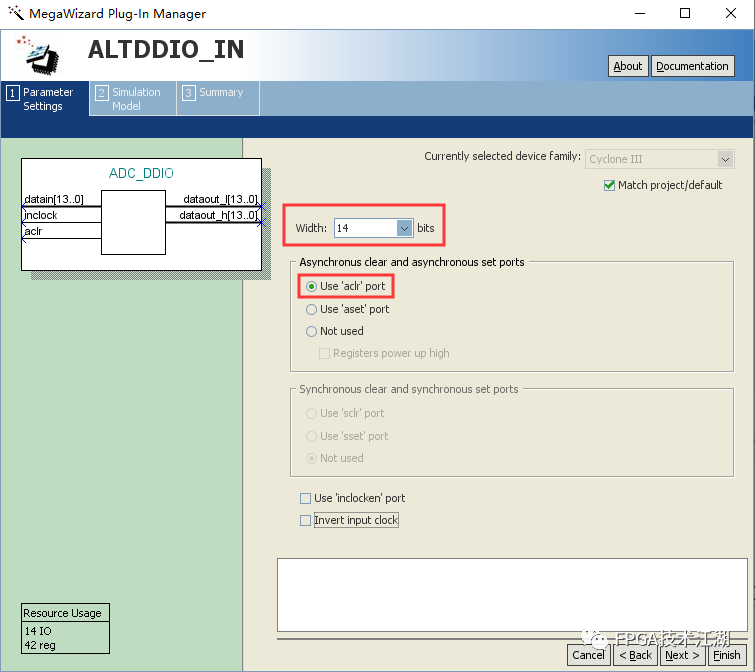
If the selected ADC is 14 bits, the data bus width is set to 14 bits, and asynchronous clear is chosen without selecting the data enable port, the first bit of data will be sampled on the falling edge of the input clock, and conversely, it will be sampled on the rising edge.
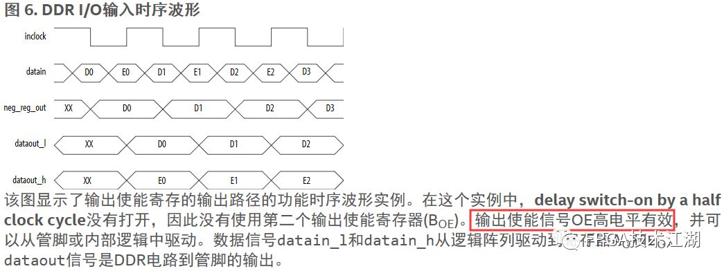
When using DDIO IP, it is important to note that the OE signal is active low in the chip, but the Quartus II software automatically adds an inverter before the output to make OE active high. If necessary, the OE can be converted back to active low.
Therefore, using DDIO IP is a common practice in communication, being fast and precise. The generated I/Q signals can be directly transmitted to the digital down-conversion (DDC) module for processing, making it convenient and quick.
Disclaimer:This article is reproduced from the FPGA Technology Jianghu WeChat public account. For issues related to content, copyright, and others, please contact the staff via WeChat (13237418207). We will respond promptly to your request for deletion!Submissions/Recruitment/Advertising/Course Collaboration/Resource Exchange, please add WeChat: 13237418207
Scan the code to add customer service WeChat, note “ Join Group“ to bring you into the education official group for technical discussions and questions and insights~