Software Platform: vivado+sdk
Hardware Platform: zynq (zedboard)
Without further ado, here is the circuit:
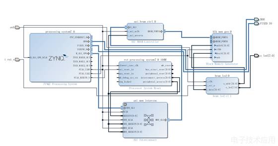
This design utilizes zynq, Axi BRAM Controller, and a Block RAM. To verify on the board, a small module bram_led has been added, which reads from PortB and displays on the LED.
The code for bram_led is somewhat rough; the specific division factor can be determined based on the configuration of fclk_clk2. It is set to 50M, thus the led will change according to the content read from bram every 1s.
Attached is the code for bram_led:
module bram_led
(
    i_clk,
    i_rst_n,
    i_data,
    o_addr,
    o_led
);
    parameter ADDR_WIDTH  = 15;
    parameter DATA_WIDTH  = 32;
    parameter COUNTER_WIDTH = 26;
    parameter CLK_COUNTER = 50000000;
    input wire i_clk;
    input wire i_rst_n;
    input wire [DATA_WIDTH - 1 :0] i_data;
    output reg [ADDR_WIDTH - 1 : 0] o_addr;
    output reg [7:0]  o_led;

    reg[COUNTER_WIDTH - 1 : 0] count;

    always@(posedge i_clk or negedge i_rst_n) begin
        if( !i_rst_n ) begin
            count <= 26'h0;
        end else if(count == CLK_COUNTER)begin
            count <= 26'h0;
        end else begin
            count <= count + 4'h4;
        end
    end

    always@(posedge i_clk or negedge i_rst_n) begin
        if( !i_rst_n ) begin
            o_addr <= 32'h00;
        end else if(count == CLK_COUNTER) begin
            o_addr <= o_addr + 4'd1;
        end else begin
            o_addr <= o_addr;
        end
    end

    always@(posedge i_clk or negedge i_rst_n) begin
        if( !i_rst_n ) begin
            o_led <= 8'h00;
        end else if(count == CLK_COUNTER) begin
            o_led <= i_data;
        end else begin
            o_led <= o_led;
        end
    end

 endmodule
The logic of AXI interconnection is automatically wired. This allows the ARM hard core on the zynq to access BRAM like memory.
In the address editor, you can configure the address of the axi bram controller, here we directly adopt the default one.

After generating the product and establishing the hdl wrapper, pull enb directly to high level, indicating it is always valid.
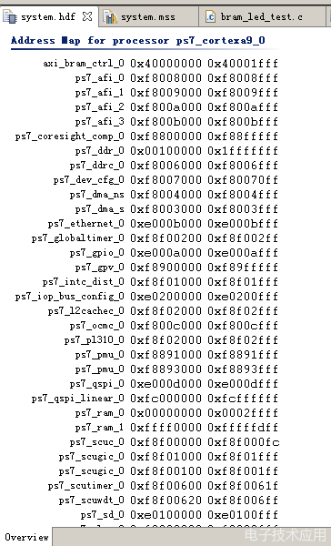
Synthesize, implement, generate bitstream and export to edk. You can see the address of the bram-controller we just configured:
Create a helloworld standalone project and input the following initialization C code for RAM:
/****************************************************************************
*
* Copyright (C) 2009 - 2014 Xilinx, Inc.  All rights reserved.
*
* Permission is hereby granted, free of charge, to any person obtaining a copy
* of this software and associated documentation files (the "Software"), to deal
* in the Software without restriction, including without limitation the rights
* to use, copy, modify, merge, publish, distribute, sublicense, and/or sell
* copies of the Software, and to permit persons to whom the Software is
* furnished to do so, subject to the following conditions:
*
* The above copyright notice and this permission notice shall be included in
* all copies or substantial portions of the Software.
*
* Use of the Software is limited solely to applications:
* (a) running on a Xilinx device, or
* (b) that interact with a Xilinx device through a bus or interconnect.
*
* THE SOFTWARE IS PROVIDED "AS IS", WITHOUT WARRANTY OF ANY KIND, EXPRESS OR
* IMPLIED, INCLUDING BUT NOT LIMITED TO THE WARRANTIES OF MERCHANTABILITY,
* FITNESS FOR A PARTICULAR PURPOSE AND NONINFRINGEMENT. IN NO EVENT SHALL
* XILINX  BE LIABLE FOR ANY CLAIM, DAMAGES OR OTHER LIABILITY,
* WHETHER IN AN ACTION OF CONTRACT, TORT OR OTHERWISE, ARISING FROM, OUT OF
* OR IN CONNECTION WITH THE SOFTWARE OR THE USE OR OTHER DEALINGS IN THE
* SOFTWARE.
*
* Except as contained in this notice, the name of the Xilinx shall not be used
* in advertising or otherwise to promote the sale, use or other dealings in
* this Software without prior written authorization from Xilinx.
*
******************************************************************************/

/*
 * helloworld.c: simple test application
 *
 * This application configures UART 16550 to baud rate 9600.
 * PS7 UART (Zynq) is not initialized by this application, since
 * bootrom/bsp configures it to baud rate 115200
 *
 * ------------------------------------------------
 * | UART TYPE   BAUD RATE                        |
 * ------------------------------------------------
 *   uartns550   9600
 *   uartlite    Configurable only in HW design
 *   ps7_uart    115200 (configured by bootrom/bsp)
 */

#include
#include "platform.h"
#include "xil_io.h"//includes Xil_Out32 function
#include "sleep.h" //includes sleep function
#define bram_base_addr 0x40000000 //base address
int main()
{
        u32 bram_offset_addr = 0x000000; //offset address
        u32 bram_data = 0x00000001; //data to write

        u32 data_read = 0;
    while(1)
    {
            while(bram_offset_addr <= 0x1fff)
            {
                        Xil_Out32(bram_base_addr + bram_offset_addr, bram_data);
                        bram_data = bram_data << 1;
                        if(bram_data == 0x100)
                        {
                                bram_data = 0x00000001;
                        }
                        bram_offset_addr += 0x04;
            }
            xil_printf("Write OK. Starting read...\r\n");
            bram_offset_addr = 0;
            while(bram_offset_addr <= 0x1ff)
            {
                        data_read = Xil_In32(bram_base_addr + bram_offset_addr);
                        //xil_printf("0X%08X\r\n", data_read);
                        bram_offset_addr += 0x04;
            }
            while(1);
    }
    return 0;
}
Then select tools–program fpga, configure the fpga properly, and then click the green run button (launch on hardware) to run the bare-metal program.
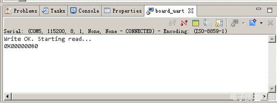
You can see the printed messages on the serial port:
If all goes well, you will see the led blinking effect!
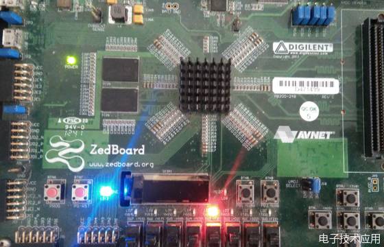
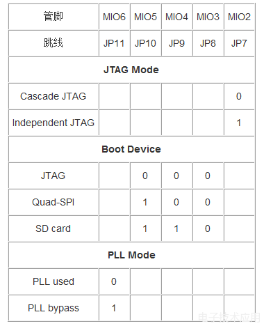
PS: When running the bare-metal program, make sure to set the board to online debugging mode, all five jumpers on the zedboard should be set to 0. Below is the specific configuration.