UART, or Universal Asynchronous Receiver/Transmitter, is one of the most commonly used communication protocols between devices. When configured correctly, UART can work with many different types of serial protocols that involve sending and receiving serial data. In serial communication, data is transmitted bit by bit over a single line or wire. In bidirectional communication, we use two wires for continuous serial data transmission. Depending on the application and system requirements, serial communication requires fewer circuits and wires, which can reduce implementation costs.
This article will illustrate the standard steps that should be followed when using UART as a hardware communication protocol, discuss the basic principles of using UART, focusing on packet transmission, standard frame protocols, and custom frame protocols; the custom frame protocol will be a value-added feature in terms of security compliance, especially during code development. During the product development process, this article will also share some basic steps to check the actual use of data sheets, aiming to help better understand and follow UART standards to maximize its capabilities and application advantages, especially when developing new products.
Communication protocols play an important role in organizing communication between devices. They are designed in different ways based on system requirements. Such protocols have specific rules that different devices follow to achieve successful communication.
By definition, UART is a hardware communication protocol that uses asynchronous serial communication at a configurable speed. Asynchronous means that there is no clock signal to synchronize the output bits entering the receiving end from the transmitting device.
Embedded systems, microcontrollers, and computers mostly use UART as a form of hardware communication protocol between devices. Among the available communication protocols, UART’s transmitter and receiver only use two lines. Although it is a widely used hardware communication method, it is not always fully optimized. When using the UART module internally in a microcontroller, the proper implementation of frame protocols is often overlooked.

Figure 1. Two UARTs Communicating Directly
The two signals of each UART device are named:
The main function of the transmitter and receiver lines of each device is to send and receive serial data for serial communication.

Figure 2. UART with Data Bus
The transmitting UART connects to a control data bus that sends data in parallel form. Then, the data will be transmitted serially, bit by bit, over the transmission line (wire) to the receiving UART. In turn, for the receiving device, the serial data will be converted back into parallel data.
UART lines serve as the communication medium for sending and receiving data. Note that UART devices have dedicated pins for sending or receiving.For UART and most serial communications, the transmitting and receiving devices need to set the baud rate to the same value. The baud rate refers to the rate at which information is transmitted to the channel. For serial ports, the set baud rate will be used as the maximum number of bits transmitted per second.Table 1 summarizes some key points about UART that must be understood.
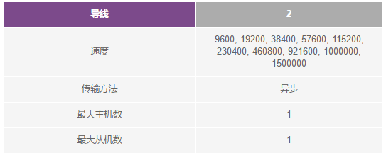
Table 1. Overview of UART
UART interfaces do not use a clock signal to synchronize the transmitter and receiver devices but transmit data asynchronously. The transmitter’s bit stream, generated by its clock signal, replaces the clock signal, and the receiver uses its internal clock signal to sample the input data. The synchronization point is managed by the same baud rate of both devices. If the baud rates are different, the timing of sending and receiving data may be affected, leading to inconsistencies in the data processing. The maximum allowable difference in baud rate is 10%; exceeding this value can cause the timing of bits to become misaligned.
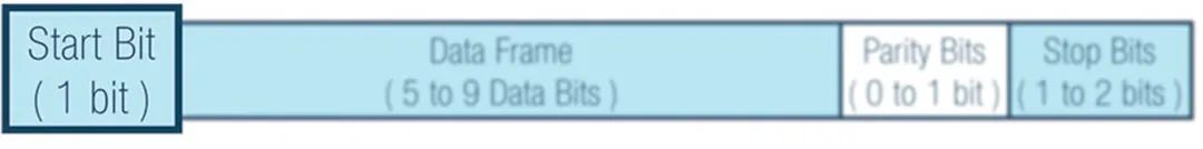
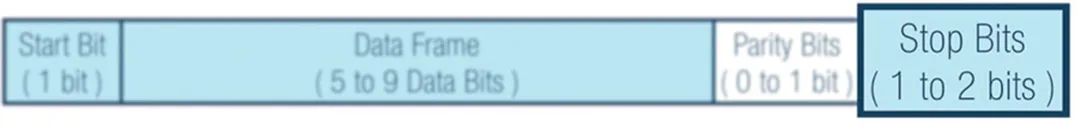
In UART, the transmission mode is in the form of packets. The mechanism connecting the transmitter and receiver includes the creation of serial data packets and the control of the physical hardware lines. A data packet consists of a start bit, data frame, parity bit, and stop bit.

Figure 3. UART Data Packet
When no data is being transmitted, the UART data transmission line typically remains at a high voltage level. To start data transmission, the transmitting UART pulls the transmission line from high to low and holds it for one clock cycle. When the receiving UART detects a high-to-low voltage transition, it begins reading the bits in the data frame at the frequency corresponding to the baud rate.
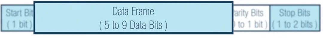
The data frame contains the actual data being transmitted. If a parity bit is used, the data frame length can be from 5 to 8 bits. If no parity bit is used, the data frame length can be 9 bits. In most cases, data is sent in a least significant bit first manner.
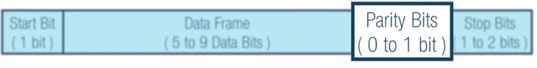
Parity describes whether a number is even or odd. By the parity bit, the receiving UART determines whether any data has changed during transmission. Electromagnetic radiation, inconsistent baud rates, or long-distance data transmission can all change data bits.
After the receiving UART reads the data frame, it counts the bits with a value of 1 and checks whether the total is even or odd. If the parity bit is 0 (even parity), the total of 1s or logical high bits in the data frame should be even. If the parity bit is 1 (odd parity), the total of 1s or logical high bits in the data frame should be odd.
When the parity bit matches the data, the UART considers the transmission error-free. However, if the parity bit is 0 and the total is odd, or the parity bit is 1 and the total is even, the UART considers that the bits in the data frame have changed.
To indicate the end of the data packet, the transmitting UART drives the data transmission line from low voltage to high voltage and holds it for 1 to 2 bit times.
Step 1: The transmitting UART receives data in parallel from the data bus.

Figure 8. Data Bus to Transmitting UART
Step 2: The transmitting UART adds the start bit, parity bit, and stop bit to the data frame.

Figure 9. UART Data Frame on Tx Side
Step 3: The entire data packet is sent serially from the transmitting UART to the receiving UART from the start bit to the stop bit. The receiving UART samples the data line at the preconfigured baud rate.

Figure 10. UART Transmission
Step 4: The receiving UART discards the start bit, parity bit, and stop bit from the data frame.

Figure 11. UART Data Frame on Rx Side
Step 5: The receiving UART converts the serial data back into parallel data and transmits it to the receiving end’s data bus.

Figure 12. Receiving UART to Data Bus
A key feature of UART is the implementation of frame protocols, which have not yet been fully utilized. Its main purpose and importance lie in providing security and protection aspects as value-added features for each device. For example, when two devices use the same UART frame protocol, it is possible to connect to the same UART without checking the configuration, and the devices may connect to different pins, which can lead to system failures.
On the other hand, implementing frame protocols ensures security because the received information must be parsed according to the designed frame protocol. Each frame protocol is specifically designed to ensure uniqueness and security.
When designing frame protocols, designers can set expected headers and footers (including CRC) for different devices. In Figure 13, 2 bytes are set as part of the header.
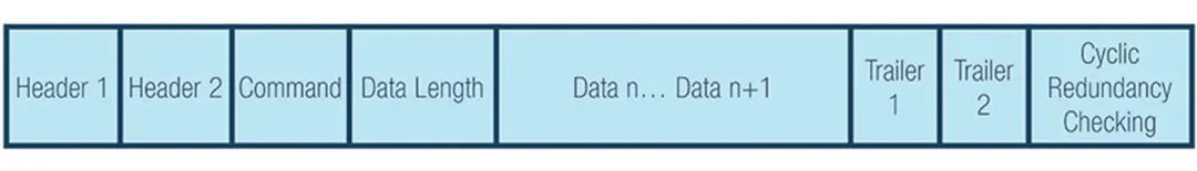
Figure 13. Example of UART Frame Protocol
According to the example, you can set unique headers, footers, and CRC for your devices.
-
Header 1 (H1 = 0xAB) and Header 2 (H2 = 0xCD)
The header is a unique identifier that determines whether you are communicating with the correct device.
The command will depend on the list of commands used to create communication between the two devices.
-
Data Length (DL) of Each Command
The data length will depend on the selected command. You can maximize the data length based on the selected command, so it will vary with the selection. In this case, the data length can be adjustable.
The data is the payload to be transmitted from the device.
-
Footer 1 (T1 = 0xE1) and Footer 2 (T2 = 0xE2)
The footer is added data after the transmission ends. Like the header, the footer can also serve as a unique identifier.
-
Cyclic Redundancy Check (CRC Formula)
The cyclic redundancy check formula is an additional error detection mode used to detect whether the original data has been accidentally changed. The CRC value from the sending device must always equal the CRC calculated value on the receiving end.
It is recommended to implement frame protocols for each UART device to enhance security, as frame protocols require the sending and receiving devices to use the same configuration.
When using any hardware communication protocol, it is essential to first check the data sheets and hardware reference manuals. Here are the steps to follow:
Step 1: Check the data sheet interface of the device.

Figure 14. Microcontroller Data Sheet
Step 2: Check the UART address under the memory mapping.
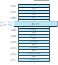
Figure 15. Microcontroller Memory Mapping
Step 3: Check specific information about the UART port, such as operating mode, data bit length, parity bit, and stop bit. The example MCU provides a full-duplex UART port that is fully compatible with the PC standard UART. The UART port offers a simplified UART interface for connecting other peripherals or hosts, supporting full duplex, DMA, and asynchronous serial data transmission. The UART port supports 5 to 8 data bits, as well as no parity, even parity, and odd parity. Frames are terminated by one or two stop bits.
Step 4: Check the details of UART operation, including baud rate calculation. The baud rate is configured using the following example formula. This formula varies by microcontroller.
Example details for UART port in the data sheet:
-
-
-
-
Programmable oversampling rate of 4, 8, 16, 32
-
Baud rate = PCLK/((M + N/2048) × 2OSR + 2 × DIV
M (DIVM Fractional Baud Rate M)
N (DIVM Fractional Baud Rate M)
UART_FBR.DIVN = 0 to 2047
Step 5: For the baud rate, be sure to check the peripheral clock (PCLK) to be used. This example has 26 MHz PCLK and 16 MHz PCLK available. Note that OSR, DIV, DIVM, and DIVN vary by device.
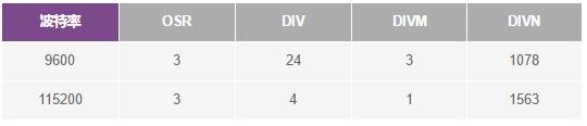
Table 2. Baud Rate Examples Based on 26 MHz PCLK
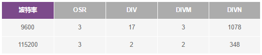
Table 3. Baud Rate Examples Based on 16 MHz PCLK
Step 6: The next part is to check the detailed registers for UART configuration. Understand the parameters involved when calculating the baud rate, such as UART_LCR2, UART_DIV, and UART_FBR. Table 4 will list the specific registers involved.
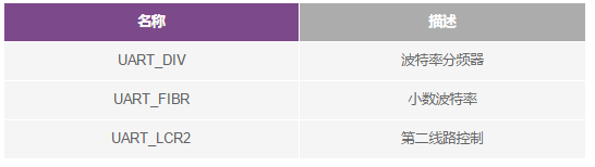
Table 4. UART Register Descriptions
Step 7: Check the details under each register, substitute values to calculate the baud rate, and then start implementing UART.
When developing robust, quality-driven products, being familiar with the UART communication protocol is highly advantageous.Knowing how to send data using only two lines, and how to transmit entire data packets or payloads, will help ensure that data is sent and received accurately.UART is the most commonly used hardware communication protocol, and having this knowledge can provide design flexibility in future designs.
You can use UART for many applications, such as:
-
Debugging: It is essential to detect system errors early during development. Adding UART allows capturing messages from the system to aid in troubleshooting.
-
Manufacturing Functional Level Tracking: Logs are very important in manufacturing. Logs can determine functionality and alert operators to what is happening on the production line.
-
Customer Updates: Software updates are crucial. A complete dynamic hardware and supporting updated software are essential for having a complete system.
-
Testing/Validation: Validating before the product leaves the manufacturing process helps ensure the highest quality product for customers.