Can SPI Use UART Communication Protocol?

Follow+Star Public Account, don’t miss out on exciting content

Can SPI Use UART Communication Protocol?

Author | strongerHuang

WeChat Official Account | strongerHuang

Recently, a reader asked this question: Can SPI use the UART custom communication protocol?
In principle: as long as the communication protocol is not directly related to the underlying communication interface (hardware), it can be used.
For example, there is a MAVLink communication protocol used for serial ports; in a product I previously developed, I directly used the CAN bus for communication, which also works.

Before sharing the main content, I would like to recommend some embedded-related positions:

Can SPI Use UART Communication Protocol?

What is a communication protocol?

A communication protocol is not difficult to understand; it is a set of rules that must be followed for communication between two (or more) devices.
According to Baidu Baike:
A communication protocol refers to the rules and agreements that both parties must follow to complete communication or services. In a data communication system with multiple different geographic locations interconnected through communication channels and devices, they must have a common language to work together to achieve information exchange and resource sharing. What to communicate, how to communicate, and when to communicate must follow mutually acceptable rules. This rule is the communication protocol.
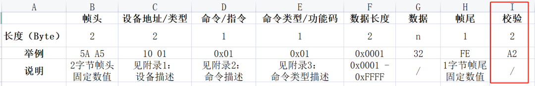
Many readers may have purchased some modules based on serial communication; many of these modules on the market use custom communication protocols, some of which are relatively simple, while others are a bit more complex.
Here’s a very simple example of a serial communication protocol: for instance, transmitting only a temperature value with a three-byte communication protocol:
Frame Head Temperature Value Frame Tail
5A One Byte Value 3B
Does this seem simple? It is also a type of communication protocol.
However, this type of communication protocol is relatively simple in application (between one pair of devices), and it has many drawbacks.

Problems Caused by Overly Simple Communication Protocols

The three-byte communication protocol above should be clear to everyone. Although it can communicate and transmit data, it has a series of problems.
For example: how to determine who to transmit to when multiple devices are connected on one bus (like RS-485)? (No device information)
Also, in a noisy environment, can you guarantee that the transmitted data is correct? (No verification information)
Furthermore, if I want to transmit multiple data of uncertain length, how should I do that? (No length information).
Those who have done custom communication will understand this series of issues.
Therefore, more “protocol information” must be agreed upon in communication protocols to ensure complete communication.

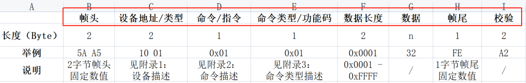
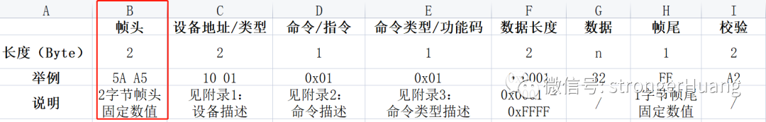
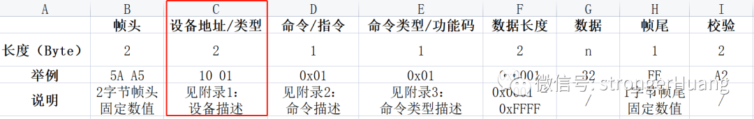
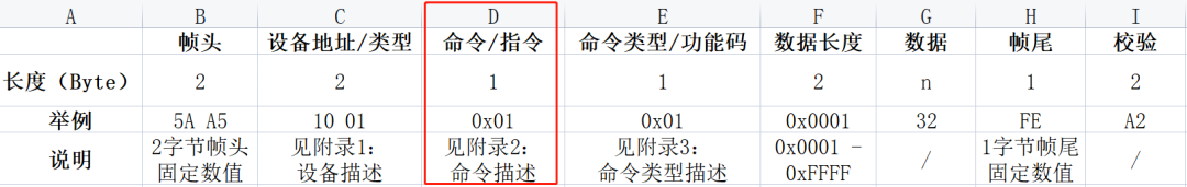
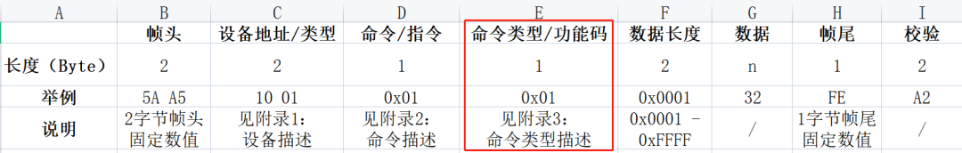
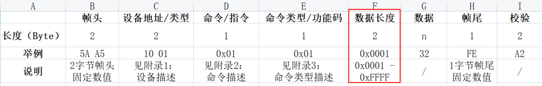
Common Contents of Communication Protocols

Serial-based communication protocols usually cannot be too complex due to the communication rate, anti-interference capability, and other factors. Compared to TCP/IP communication protocols, they are relatively lightweight.
Thus, in serial communication, aside from some common communication protocols (like Modbus, MAVLink), engineers often customize communication protocols based on their project needs.
Below are some key points regarding common custom communication protocols.

Can SPI Use UART Communication Protocol?

(This is some common protocol content; the actual content may vary in different situations)
1. Frame Head
The frame head is the beginning of a frame of communication data.
Some communication protocols have only one frame head, while others have two, such as 5A and A5 as frame heads.

Can SPI Use UART Communication Protocol?

2. Device Address/Type
The device address or type is usually used to distinguish different devices among multiple devices.

Can SPI Use UART Communication Protocol?

In this case, the protocol or appendix needs to describe various device type information for developers to query while coding.
Of course, for some fixed communication between two types of devices, this option may not be necessary.
3. Command/Instruction
Commands/instructions are common, generally using different commands to distinguish different operations.

Can SPI Use UART Communication Protocol?

For example: Temperature: 0x01; Humidity: 0x02;
4. Command Type/Function Code
This option further supplements the command. For example: read, write operations.

Can SPI Use UART Communication Protocol?

For example: Read Flash: 0x01; Write Flash: 0x02;
5. Data Length
This option for data length may be placed before the device address in some protocols, counting the command information as part of the “length”.
This is mainly to facilitate the protocol (receiver) in parsing, by keeping track of the received data length.

Can SPI Use UART Communication Protocol?

For example: sometimes transmitting one valid data, sometimes transmitting multiple valid data, or even transmitting an array of data. In this case, the transmitted frame data is variable length, and must have [data length] to constrain it.
Some lengths are one byte, with a range of: 0x01 ~ 0xFF; some may require more to be transmitted at once, using two bytes to represent a range of 0x0001 ~ 0xFFFFF.
Of course, some protocols have a fixed length (like only transmitting temperature and humidity), which may not have this option.
6. Data
Data does not need further description; it is the actual data you transmit, like temperature: 25℃.
7. Frame Tail
Some protocols may not have a frame tail; this is an optional element.
8. Checksum
The checksum is a relatively important element; generally, a more formal communication protocol includes this option for a simple reason: communication is easily affected by interference or other reasons, leading to data transmission errors.
If there is a checksum, it can effectively avoid errors in data transmission.

Can SPI Use UART Communication Protocol?

There are many methods for checksums, such as checksums and CRC checks, which are common verification methods in custom protocols.
Additionally, some protocols may place the checksum before the last frame tail.

Code Implementation of Communication Protocol

Custom communication protocol code implementations can take many forms; there are various ways to achieve the same goal.
Of course, while implementing, you need to consider the actual situation of your project, such as if the communication data is large, you may need to use a message queue (FIFO), or if the protocol is complex, it’s better to encapsulate structures, etc.
Below are some codes I have used previously; they may not describe more details, but some ideas can be referenced.
1. Sending Message Data
a. Directly sending each byte via serial port
This is understandable even for beginners; here’s an example from the DGUS serial screen:
#define DGUS_FRAME_HEAD1          0xA5                     // DGUS screen frame head 1#define DGUS_FRAME_HEAD2          0x5A                     // DGUS screen frame head 2
#define DGUS_CMD_W_REG            0x80                     // DGUS write register command
#define DGUS_CMD_R_REG            0x81                     // DGUS read register command
#define DGUS_CMD_W_DATA           0x82                     // DGUS write data command
#define DGUS_CMD_R_DATA           0x83                     // DGUS read data command
#define DGUS_CMD_W_CURVE          0x85                     // DGUS write curve command
/* DGUS Register Addresses */
#define DGUS_REG_VERSION          0x00                     // DGUS version
#define DGUS_REG_LED_NOW          0x01                     // LED backlight brightness
#define DGUS_REG_BZ_TIME          0x02                     // Buzzer duration
#define DGUS_REG_PIC_ID           0x03                     // Display page ID
#define DGUS_REG_TP_FLAG          0x05                     // Touch coordinate update flag
#define DGUS_REG_TP_STATUS        0x06                     // Coordinate status
#define DGUS_REG_TP_POSITION      0x07                     // Coordinate position
#define DGUS_REG_TPC_ENABLE       0x0B                     // Touch enable
#define DGUS_REG_RTC_NOW          0x20                     // Current RTC
// Write one byte data to the specified register of DGUS screen
void DGUS_REG_WriteWord(uint8_t RegAddr, uint16_t Data){  DGUS_SendByte(DGUS_FRAME_HEAD1);  DGUS_SendByte(DGUS_FRAME_HEAD2);  DGUS_SendByte(0x04);
  DGUS_SendByte(DGUS_CMD_W_REG);                 // Command  DGUS_SendByte(RegAddr);                        // Address
  DGUS_SendByte((uint8_t)(Data>>8));             // Data  DGUS_SendByte((uint8_t)(Data&0xFF));}
// Write one byte data to the specified address of DGUS screen
void DGUS_DATA_WriteWord(uint16_t DataAddr, uint16_t Data){  DGUS_SendByte(DGUS_FRAME_HEAD1);  DGUS_SendByte(DGUS_FRAME_HEAD2);  DGUS_SendByte(0x05);
  DGUS_SendByte(DGUS_CMD_W_DATA);                // Command
  DGUS_SendByte((uint8_t)(DataAddr>>8));         // Address  DGUS_SendByte((uint8_t)(DataAddr&0xFF));
  DGUS_SendByte((uint8_t)(Data>>8));             // Data  DGUS_SendByte((uint8_t)(Data&0xFF));}
b. Sending via message queue
Based on the above, use a buffer to hold the message, then “pack” it into the message queue and send it out via FIFO.
static uint8_t  sDGUS_SendBuf[DGUS_PACKAGE_LEN];
// Write one byte data to the specified register of DGUS screen
void DGUS_REG_WriteWord(uint8_t RegAddr, uint16_t Data){  sDGUS_SendBuf[0] = DGUS_FRAME_HEAD1;           // Frame head  sDGUS_SendBuf[1] = DGUS_FRAME_HEAD2;  sDGUS_SendBuf[2] = 0x06;                       // Length  sDGUS_SendBuf[3] = DGUS_CMD_W_CTRL;            // Command  sDGUS_SendBuf[4] = RegAddr;                    // Address  sDGUS_SendBuf[5] = (uint8_t)(Data>>8);         // Data  sDGUS_SendBuf[6] = (uint8_t)(Data&0xFF);
  DGUS_CRC16(&sDGUS_SendBuf[3], sDGUS_SendBuf[2] - 2, &sDGUS_CRC_H, &sDGUS_CRC_L);  sDGUS_SendBuf[7] = sDGUS_CRC_H;                // Checksum  sDGUS_SendBuf[8] = sDGUS_CRC_L;
  DGUSSend_Packet_ToQueue(sDGUS_SendBuf, sDGUS_SendBuf[2] + 3);}
// Write one byte data to the specified address of DGUS screen
void DGUS_DATA_WriteWord(uint16_t DataAddr, uint16_t Data){  sDGUS_SendBuf[0] = DGUS_FRAME_HEAD1;           // Frame head  sDGUS_SendBuf[1] = DGUS_FRAME_HEAD2;  sDGUS_SendBuf[2] = 0x07;                       // Length  sDGUS_SendBuf[3] = DGUS_CMD_W_DATA;            // Command  sDGUS_SendBuf[4] = (uint8_t)(DataAddr>>8);     // Address  sDGUS_SendBuf[5] = (uint8_t)(DataAddr&0xFF);  sDGUS_SendBuf[6] = (uint8_t)(Data>>8);         // Data  sDGUS_SendBuf[7] = (uint8_t)(Data&0xFF);
  DGUS_CRC16(&sDGUS_SendBuf[3], sDGUS_SendBuf[2] - 2, &sDGUS_CRC_H, &sDGUS_CRC_L);  sDGUS_SendBuf[8] = sDGUS_CRC_H;                // Checksum  sDGUS_SendBuf[9] = sDGUS_CRC_L;
  DGUSSend_Packet_ToQueue(sDGUS_SendBuf, sDGUS_SendBuf[2] + 3);}
c. Using “struct” instead of “array SendBuf” method
Structures are more convenient for reference and management than arrays, so the struct method is more advanced and practical compared to an array buffer. (Of course, if there are many members, using temporary variables can also lead to excessive stack usage)
For example:
typedef struct{  uint8_t  Head1;                 // Frame head 1  uint8_t  Head2;                 // Frame head 2  uint8_t  Len;                   // Length  uint8_t  Cmd;                   // Command  uint8_t  Data[DGUS_DATA_LEN];   // Data  uint16_t CRC16;                 // CRC check}DGUS_PACKAGE_TypeDef;
d. More
There are many ways to send data via serial port, such as using DMA instead of message queue.
2. Receiving Message Data
Serial message reception is usually done through serial interrupts, though polling methods are also occasionally used.
a. Regular Interrupt Reception
Taking the DGUS serial screen as an example, here’s a simple and common interrupt reception method:
void DGUS_ISRHandler(uint8_t Data){  static uint8_t sDgus_RxNum = 0;                // Count  static uint8_t sDgus_RxBuf[DGUS_PACKAGE_LEN];  static portBASE_TYPE xHigherPriorityTaskWoken = pdFALSE;
  sDgus_RxBuf[gDGUS_RxCnt] = Data;  gDGUS_RxCnt++;
  /* Check Frame Head */  if(sDgus_RxBuf[0] != DGUS_FRAME_HEAD1)       // Received Frame Head 1  {    gDGUS_RxCnt = 0;    return;  }  if((2 == gDGUS_RxCnt) && (sDgus_RxBuf[1] != DGUS_FRAME_HEAD2))  {    gDGUS_RxCnt = 0;    return;  }
  /* Determine One Frame Data Length */  if(gDGUS_RxCnt == 3)  {    sDgus_RxNum = sDgus_RxBuf[2] + 3;  }
  /* Received One Frame Data */  if((6 <= gDGUS_RxCnt) && (sDgus_RxNum <= gDGUS_RxCnt))  {    gDGUS_RxCnt = 0;
    if(xDGUSRcvQueue != NULL)                    // Parse successful, add to queue    {      xQueueSendFromISR(xDGUSRcvQueue, &sDgus_RxBuf[0], &xHigherPriorityTaskWoken);      portEND_SWITCHING_ISR(xHigherPriorityTaskWoken);    }  }}

b. Adding Timeout Detection

Receiving data might be interrupted for some reason; thus, timeout detection is very necessary.

For example: use an extra MCU timer to handle timeout counting; when receiving data, start counting, and if no data is received for over 1ms, discard the previous data package.

static void DGUS_TimingAndUpdate(uint16_t Nms){  sDGUSTiming_Nms_Num = Nms;  TIM_SetCounter(DGUS_TIM, 0);                   // Set counter value to 0  TIM_Cmd(DGUS_TIM, ENABLE);                     // Start timer}
void DGUS_COM_IRQHandler(void){  if((DGUS_COM->SR & USART_FLAG_RXNE) == USART_FLAG_RXNE)  {    DGUS_TimingAndUpdate(5);                     // Update timeout (to prevent timeout)    DGUS_ISRHandler((uint8_t)USART_ReceiveData(DGUS_COM));  }}

c. More

Similar to sending, there are many implementation methods for receiving, such as using the struct method. However, all implementations need to be tailored to your specific needs.

Conclusion

The above custom protocol content is for reference only; the final choices and byte usage depend on your actual needs.
Custom communication protocols based on serial communication vary widely, such as MCU processing capabilities, the number of devices, communication content, etc., all influence your custom protocol.
Some may only require a very simple communication protocol to meet requirements, while others may need a more complex protocol.
Finally, two points to emphasize:
1. The examples provided are not complete codes (some details are not described), primarily for learning programming concepts or implementation methods.
2. A good communication protocol code must have certain fault tolerance measures, such as: send completion detection, receive timeout detection, data error detection, etc. Thus, the above code is not complete.

———— END ————

Can SPI Use UART Communication Protocol?

● Column “Embedded Tools”

● Column “Embedded Development”

● Column “Keil Tutorial”

● Selected Tutorials from Embedded Column

Follow the public account and reply “Join Group” to join the technical exchange group according to the rules, reply “1024” for more content.

Can SPI Use UART Communication Protocol?

Can SPI Use UART Communication Protocol?

Click “Read Original” for more shares.

Leave a Comment