Introduction
Previously, we introduced the basic knowledge of I2C and SPI. In this chapter, we will discuss UART (Universal Asynchronous Receiver/Transmitter), which is used for communication between internal and external devices of a computer. Data transmission within a computer is parallel, while data transmission with external devices is often serial. Therefore, a chip is needed as a medium to solve this issue. UART can achieve this functionality by converting parallel data from the computer into serial output and converting serial data from external devices into parallel input. In a sense, UART can be considered a “device” rather than a true bus, but as a type of communication protocol, it is included in this topic.
Definition
UART stands for Universal Asynchronous Receiver/Transmitter, which is a full-duplex, asynchronous communication interface that operates at the data link layer and supports standards such as RS232 and RS485. Although UART can convert between serial and parallel data, it is still a serial interface.
-
Serial and Parallel Data Conversion Data is transmitted in parallel within a computer, while external devices generally handle data in a serial manner. When a computer communicates with external devices in a serial manner, a conversion between serial and parallel is necessary. When sending data, parallel data from the CPU is converted into serial data through a parallel input, serial output shift register before being sent to external devices. When receiving data, the received serial data is converted into parallel data through a serial input, parallel output shift register before being sent to the CPU.
-
Full Duplex, Asynchronous UART has separate pins for sending and receiving, allowing simultaneous data transmission and reception. I2C and SPI buses operate synchronously, where both the master and slave devices use the same clock signal. Data is sent after a “synchronization signal” is sent; for example, I2C sends the slave device address first, and SPI sends the chip select signal first. Because the master and slave devices use the same clock signal, their rhythms remain consistent. Once the communication is established, data can be sent without needing start and stop bits until the data transmission ends. However, asynchronous communication is different; the time intervals between characters are unpredictable, and the receiver does not know when the data will arrive, so it must always be prepared. This requires adding start and stop bits to each character sent to ensure accurate data reception.
-
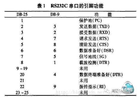
Pin Description Taking RS232 as an example, there are two types of serial port pins: 9-pin and 25-pin, with the 25-pin primarily used for early devices and gradually being phased out. In practical use, only three wires (transmit, receive, and ground) are generally required for data transmission. Connecting the device’s TXD/RXD with the computer’s RXD/TXD allows for full-duplex transmission. As seen in the table, there is no clock line, indicating that UART is asynchronous. While collecting information, I came across an article that provided detailed explanations of pin descriptions, which may be of interest. Detailed Explanation of Device Monitoring Technology.
-
Distinguishing UART, USART, and SCI There are two types of hardware available for UART in the market: those that support asynchronous communication only and those that support both asynchronous and synchronous communication. The former is the literal meaning of UART, referred to as Serial Communication Interface (SCI) in Motorola microcontrollers; Universal Synchronous/Asynchronous Receiver/Transmitter (USART) in Microchip microcontrollers and UART in Fujitsu microcontrollers are two typical examples of the latter.
-
USART (Universal Synchronous/Asynchronous Receiver/Transmitter) is a universal synchronous and asynchronous receiver/transmitter that can operate in both asynchronous and synchronous modes. Since it can operate in synchronous mode, a synchronization clock is needed, and USART includes a clock generator to provide the main clock.
-
SCI (Serial Communication Interface) is a serial communication interface in contrast to parallel communication, representing a general term for serial communication technology, initially proposed by Motorola. In a sense, UART can also be considered a type of SCI. The communication protocol of SCI is primarily reflected in the data format. In SCI, data characters with format information are referred to as a frame of data, and the data format mainly includes 1 start bit, 1-8 data bits, 1 parity bit, 1-2 stop bits, and additional bits to distinguish between address and data. These can be configured through the SCI communication control register SCICCR, which defines the data format used during communication.
-
RS232/RS485 RS232 and RS485 are both physical interface electrical standards in serial communication, specifying transmission media (cables), transceiver levels, etc. In fact, UART is just a communication protocol, and specific data transmission requires dedicated transmission circuits. UART operates at the data link layer, while RS232/RS485 operates at the physical layer, indicating that RS232/RS485 and UART are relatively independent. For example, RS232 specifies signal transmission levels; logic high level is -3V to -15V with load, and -25V without load; logic low level is +3V to +15V with load, and +25V without load. Generally, personal desktop computers have two sets of RS-232 interfaces, referred to as COM1 and COM2. However, RS232 can only be used for point-to-point communication and cannot support networking; moreover, most computers and I/O interface chips now use TTL levels (0-0.8V for logic 0, +2.0V-+5.0V for logic 1), so a dedicated level conversion circuit must be designed when using RS232.
Under these conditions, the new interface standard RS485 was developed. RS485 represents a logic 1 with a voltage difference of +(2-6)V between the two wires and logic 0 with a voltage difference of -(2-6)V. The signal levels of RS-485 are lower than RS-232, making it less likely to damage the interface circuit chips, and this level is compatible with TTL levels, facilitating connection with TTL circuits.
Communication Protocol
-
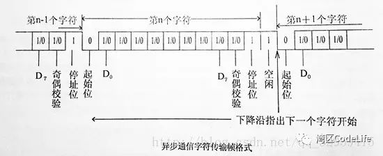
Data Format Because UART is asynchronous transmission, each character transmitted requires a specific format. To ensure correct transmission, UART has defined its own data format. For each character transmitted, the data format can be defined by the following data bits.
-
Start Bit: When data is to be sent, the data signal line changes to a low level and remains low for a while, indicating the start of a character. This bit is called the start bit.
-
Data Bits: Immediately following the start bit, each bit of the character to be sent appears sequentially on the signal line, with the least significant bit D0 appearing first, thus being sent first. Different coding schemes may have different numbers of data bits, which can be 4, 5, 6, 7, 8, etc.; when characters are represented in ASCII, the data bits occupy 7 bits (D0-D7).
-
Parity Bit: Adding this bit to the data bits ensures that the number of “1” bits is even (even parity) or odd (odd parity) to verify the correctness of the data transmission. For example, if odd parity is used and the number of “1” bits is odd, this bit is set to “0”; otherwise, it is set to “1”. Of course, parity can also be omitted in the system.
-
Stop Bit: This is a character data end marker and can be 1, 1.5, or 2 bits of high level. Because data is timed on the transmission line, and each device has its own clock, there may be slight desynchronization between two devices during communication. Therefore, the stop bit not only indicates the end of transmission but also provides an opportunity for the computer to correct clock synchronization. The more stop bits used, the greater the tolerance for clock synchronization discrepancies, but the data transmission rate will also decrease. There should be at least one high level after the parity bit to indicate the stop bit. If another character is transmitted immediately after one character is completed, the start bit of the next character will follow the stop bit of the previous character; otherwise, the line will enter an idle state after the stop bit.
-
Idle Bit: This is in a logic “1” state, indicating that there is currently no data being transmitted on the line.
Thus, when sending a 7-bit ASCII character in asynchronous mode, 10, 10.5, or 11 bits are actually sent. If 10 bits are used for transmission, it means that 30% of the transmission time will be wasted; this problem does not occur in synchronous transmission.
-
Baud Rate The baud rate indicates the speed of data transmission, defined as the number of data bits transmitted per second in the computer. For example, if the baud rate is set to 9600, and each character consists of 1 start bit, 7 data bits, 1 parity bit, and 1 stop bit, totaling 10 data bits, then 960 characters can be transmitted per second (9600/10=960).
Working Principle
-
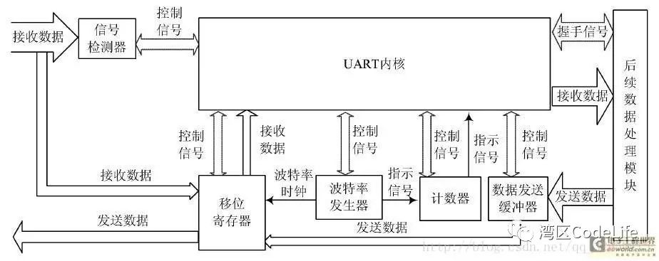
Basic Structure
-
Output Buffer Register: Receives parallel data sent from the data bus by the CPU and stores it.
-
Output Shift Register: Receives parallel data from the output buffer and shifts it out bit by bit at the transmission clock rate, converting parallel data into serial data output.
-
Input Shift Register: Shifts in the data appearing on the serial data input line bit by bit at the receiving clock rate. When the data is full, it is sent to the input buffer as parallel data, converting serial data into parallel data.
-
Input Buffer Register: Receives parallel data from the input shift register, which is then retrieved by the CPU.
-
Control Register: Receives control words sent by the CPU, determining the transmission method and data format during communication. For example, whether to use asynchronous or synchronous mode, the number of bits in the data character, whether to include parity, and the number of stop bits.
-
Status Register: Stores various status information of the interface, such as whether the output buffer is empty or if input characters are ready. During communication, when a certain condition is met, the status detection logic in the interface sets the corresponding bit in the status register to “1” for the CPU to query.
-
Receiving Data When UART receives data, the receiving circuit continuously monitors the serial input terminal RxD. When a start bit appears on the data line, the character reception process begins, converting the serial data into parallel data according to the corresponding format and sending it to the input buffer for the CPU to read. If a parity bit is set, it can also perform parity checking during data transmission and automatically detect the stop bit for each character. If there is no stop bit, the frame error flag FRERR is set.
-
Sending Data When UART sends data, the output buffer adds the corresponding control information (start bit, parity bit, stop bit, etc.) to the parallel data from the CPU, and under the control of clock pulses, converts it into serial data through the parallel/serial conversion circuit, sending it out bit by bit from the TxD pin. To allow the CPU to correctly control data reception and transmission, the circuit also has status information such as data ready and output buffer empty.
-
Working Modes UART has two commonly used methods for receiving data: interrupt and polling. When an interrupt detects that data is received, it generates a receive interrupt to process the data; polling means checking periodically to see if there is data to be processed.
-
Interrupt: In UART communication, the interrupt method is relatively efficient. When data needs to be received, it triggers an interrupt to process the data, promptly retrieving the buffered data. In the early days without FIFO, UART generated an interrupt for every character received and sent, which clearly burdened the CPU due to the frequent interrupt operations. However, with FIFO, interrupts can be triggered after multiple data transactions, allowing for unified processing, significantly improving transmission efficiency. Generally, an interrupt is triggered when the FIFO is full, but if the data volume is small or the sending end has long intervals between transmissions, a timeout interrupt may be used to process the data.
-
Polling: Polling means checking every certain period whether there is data to process. This method is less real-time compared to interrupts, and for devices without FIFO, if characters are not retrieved promptly, they may be overwritten by subsequent data, leading to errors. Therefore, polling is generally used when real-time data processing is not critical or when frequent interrupt operations heavily impact the CPU. However, with FIFO, the problem of data loss in polling has been greatly improved.
Conclusion
UART is a key component of serial communication ports in computers and is a highly representative interface of SCI (Serial Communication Interface) with many applications. It is worth mentioning that UART generally has a loopback mode for diagnostics or debugging. In loopback mode, data sent from Tx is received at the Rx input, which is quite useful during serial port debugging.