I2C (Inter-Integrated Circuit) is a serial communication protocol used for short-distance communication, typically for data transmission between microcontrollers and various peripheral devices (such as sensors, displays, memory, etc.).
Characteristics of the I2C Protocol
The I2C protocol has several notable features:
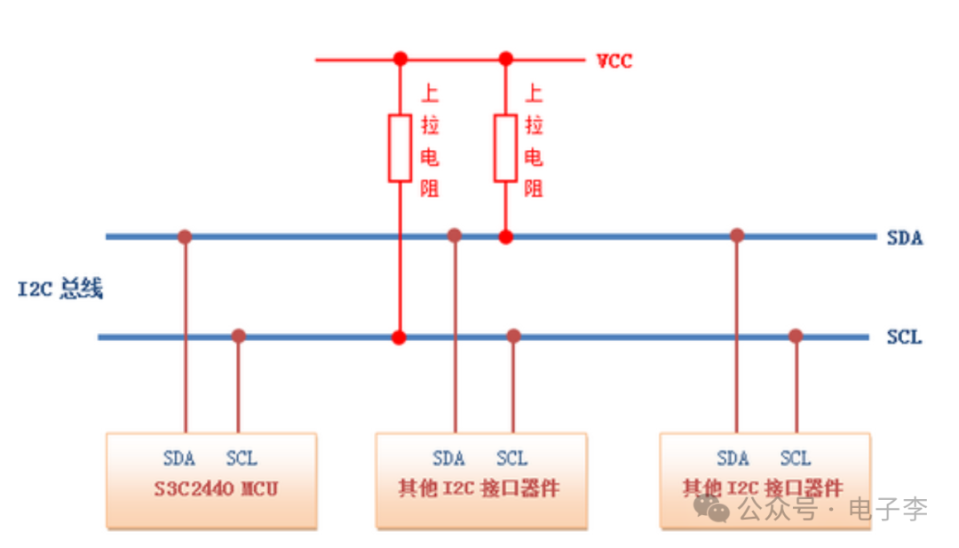
Two-wire Communication: The I2C protocol uses only two signal lines: SDA (data line) and SCL (clock line).
Multi-master and Multi-slave: The I2C bus supports multiple master devices and multiple slave devices, allowing for flexible configuration.
Addressing Mechanism: Each slave device has a unique address, and the master device selects which slave device to communicate with using the address.
Synchronous Communication: The I2C protocol is a synchronous communication protocol, with the clock signal controlled by the master device while the slave device passively receives.
Working Principle of the I2C Protocol
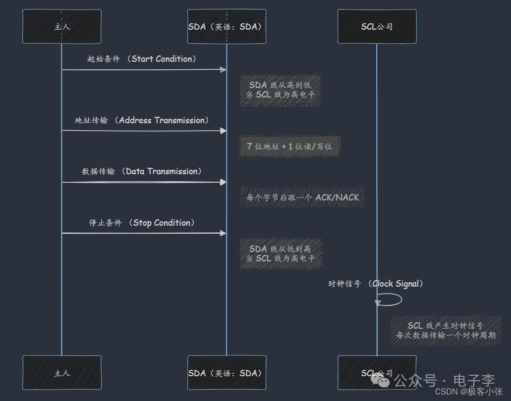
The working principle of the I2C protocol can be divided into the following steps:
Start Condition: The master device pulls the SDA line low while keeping the SCL line high, indicating the start of communication.
Address Transmission: The master device sends the address of the slave device, including a read/write bit, and the slave responds according to the address.
Data Transmission: Data is transmitted between the master and slave devices, with 8 bits of data transmitted at a time, confirmed by an ACK/NACK bit to indicate data reception status.
Stop Condition: The master device pulls the SDA line high while keeping the SCL line high, indicating the end of communication.
Timing Diagram of the I2C Protocol
To better understand the working principle of the I2C protocol, let’s take a look at the timing diagram of the I2C protocol:
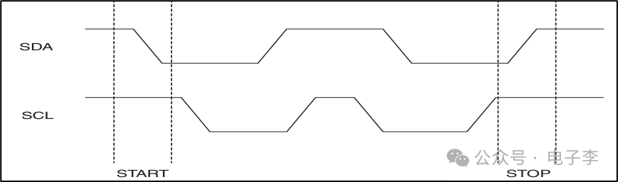
1)Start and Stop Signals
When SCL is high, a falling edge on SDA indicates the start bit; when SCL is high, a rising edge on SDA indicates the stop bit, as shown in the figure below:

2)Data Validity
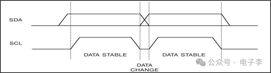
The I2C bus must ensure that the data on SDA remains stable during the high level of SCL; thus, changes on SDA can only occur while SCL is low.
3)ACK and NACK
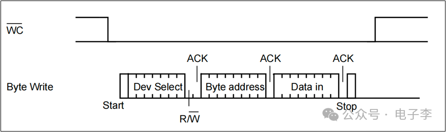
4)Byte Write Timing
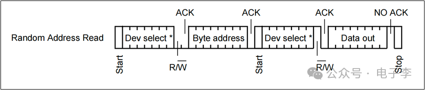
5)Byte Read Timing
6)Single Write Multiple Bytes Timing
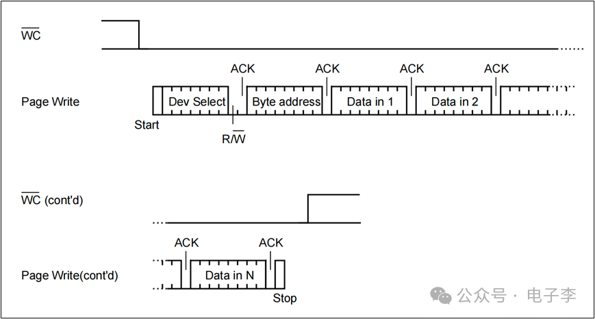
Writing multiple bytes at once is also called Page Write. The AT24C02 has only 16 bytes per page, and can only write to a single page at a time, so a maximum of 16 bytes can be written at once. If more than 16 bytes are written at once, the excess will be rewritten from the start address of this page.
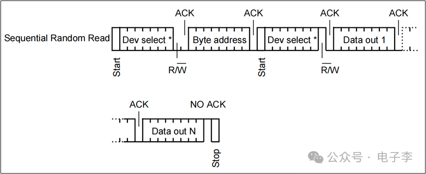
7)Single Read Multiple Bytes Timing
When reading multiple bytes, there is no limit on the number of bytes that can be read.
I2C Protocol Applications
The I2C protocol is widely used in IoT microcontrollers. Here are some common application scenarios:
Sensor Data Acquisition: The I2C protocol is commonly used to read data from various sensors (such as temperature sensors, humidity sensors, pressure sensors, etc.).
Display Control: The I2C protocol can be used to control OLED, LCD, and other displays to show various information.
Memory Access: The I2C protocol can be used to access EEPROM, FRAM, and other non-volatile memories to store and read data.
Clock Chips: The I2C protocol is often used to communicate with real-time clock (RTC) chips to obtain the current time and date.
Note: On the I2C bus, the SDA and SCL lines need to be connected to the power supply through pull-up resistors (usually 4.7kΩ) to ensure signal stability.
Programming Implementation of the I2C Protocol
How to implement the I2C protocol on a microcontroller. We take the STM32 microcontroller as an example, using the HAL library for I2C communication.
1) Initialize the I2C Peripheral
First, the I2C peripheral needs to be initialized. Below is the initialization code:
#include "stm32f1xx_hal.h"// I2C handleI2C_HandleTypeDef hi2c1;// I2C initialization functionvoid I2C_Init(void) { hi2c1.Instance = I2C1; hi2c1.Init.ClockSpeed = 100000; // I2C clock frequency is 100kHz hi2c1.Init.DutyCycle = I2C_DUTYCYCLE_2; hi2c1.Init.OwnAddress1 = 0; hi2c1.Init.AddressingMode = I2C_ADDRESSINGMODE_7BIT; hi2c1.Init.DualAddressMode = I2C_DUALADDRESS_DISABLE; hi2c1.Init.OwnAddress2 = 0; hi2c1.Init.GeneralCallMode = I2C_GENERALCALL_DISABLE; hi2c1.Init.NoStretchMode = I2C_NOSTRETCH_DISABLE; if (HAL_I2C_Init(&hi2c1) != HAL_OK) { // Initialization failed, handle error Error_Handler(); }}2) Sending Data
How to send data via I2C. Below is the code for sending data:
#include "stm32f1xx_hal.h"// I2C handleextern I2C_HandleTypeDef hi2c1;// Send data functionvoid I2C_SendData(uint8_t deviceAddress, uint8_t registerAddress, uint8_t *data, uint16_t size) { if (HAL_I2C_Mem_Write(&hi2c1, deviceAddress, registerAddress, I2C_MEMADD_SIZE_8BIT, data, size, HAL_MAX_DELAY) != HAL_OK) { // Sending data failed, handle error Error_Handler(); }}3) Receiving Data
How to receive data via I2C. Below is the code for receiving data:
#include "stm32f1xx_hal.h"// I2C handleextern I2C_HandleTypeDef hi2c1;// Receive data functionvoid I2C_ReceiveData(uint8_t deviceAddress, uint8_t registerAddress, uint8_t *data, uint16_t size) { if (HAL_I2C_Mem_Read(&hi2c1, deviceAddress, registerAddress, I2C_MEMADD_SIZE_8BIT, data, size, HAL_MAX_DELAY) != HAL_OK) { // Receiving data failed, handle error Error_Handler(); }}Debugging Tips for the I2C Protocol
In actual development, debugging I2C communication issues may present some challenges. Here are some common debugging tips:
Check Hardware Connections: Ensure that the SDA and SCL lines are properly connected and that the pull-up resistors are connected to the power supply.
Use an Oscilloscope or Logic Analyzer: Observe the signals on the I2C bus using an oscilloscope or logic analyzer to check for incorrect timing or data.
Check Device Address: Ensure that the address of the slave device sent by the master device is correct and that it matches the actual device address.
Check ACK/NACK Signals: During data transmission, check whether the slave device correctly responds with ACK/NACK signals.
Advanced Applications of the I2C Protocol
In addition to basic I2C communication, the I2C protocol has some advanced applications. For example:
Multi-master Communication: Multiple master devices can communicate on the I2C bus. It is important to note that multi-master communication requires handling bus arbitration issues.
Clock Stretching: Slave devices can extend the clock cycle by pulling the SCL line low to process data. This mechanism is called clock stretching.
Fast Mode and High-Speed Mode: The I2C protocol supports higher communication rates of 400kHz and 3.4MHz, respectively.
Example Project: Temperature and Humidity Sensor
Using the I2C protocol to read data from a temperature and humidity sensor.
Assuming we are using the DHT12 temperature and humidity sensor, which communicates with the microcontroller via the I2C interface. Below is the specific code implementation:
1) Initialize the I2C Peripheral
#include "stm32f1xx_hal.h"// I2C handleI2C_HandleTypeDef hi2c1;// I2C initialization functionvoid I2C_Init(void) { hi2c1.Instance = I2C1; hi2c1.Init.ClockSpeed = 100000; // I2C clock frequency is 100kHz hi2c1.Init.DutyCycle = I2C_DUTYCYCLE_2; hi2c1.Init.OwnAddress1 = 0; hi2c1.Init.AddressingMode = I2C_ADDRESSINGMODE_7BIT; hi2c1.Init.DualAddressMode = I2C_DUALADDRESS_DISABLE; hi2c1.Init.OwnAddress2 = 0; hi2c1.Init.GeneralCallMode = I2C_GENERALCALL_DISABLE; hi2c1.Init.NoStretchMode = I2C_NOSTRETCH_DISABLE; if (HAL_I2C_Init(&hi2c1) != HAL_OK) { // Initialization failed, handle error Error_Handler(); }}2) Read Temperature and Humidity Data
#include "stm32f1xx_hal.h"// I2C handleextern I2C_HandleTypeDef hi2c1;// Function to read temperature and humidity datavoid Read_Temperature_Humidity(uint8_t *temperature, uint8_t *humidity) { uint8_t deviceAddress = 0x5C << 1; // DHT12 device address uint8_t registerAddress = 0x00; // Data register address uint8_t data[5]; // Data buffer // Read data if (HAL_I2C_Mem_Read(&hi2c1, deviceAddress, registerAddress, I2C_MEMADD_SIZE_8BIT, data, 5, HAL_MAX_DELAY) != HAL_OK) { // Reading data failed, handle error Error_Handler(); } // Parse temperature and humidity data *humidity = data[0]; *temperature = data[2];}3) Main Function
#include "stm32f1xx_hal.h"#include <stdio.h>// Declaration of I2C initialization functionvoid I2C_Init(void);// Declaration of function to read temperature and humidity datavoid Read_Temperature_Humidity(uint8_t *temperature, uint8_t *humidity);int main(void) { // Initialize HAL library HAL_Init(); // Initialize I2C peripheral I2C_Init(); // Temperature and humidity variables uint8_t temperature = 0; uint8_t humidity = 0; // Read temperature and humidity data Read_Temperature_Humidity(&temperature, &humidity); // Output temperature and humidity data printf("Temperature: %d°C\n", temperature); printf("Humidity: %d%%\n", humidity); while (1) { // Main loop }}Copyright Statement: This account maintains a neutral stance on all original and reprinted articles’ statements and viewpoints. The articles pushed are for readers’ learning and communication purposes only. The copyrights of articles, images, etc., belong to the original authors. If there is any infringement, please contact for deletion.
Reference Link: https://blog.csdn.net/qq_40431685/article/details/139711106