

UART (Universal Asynchronous Receiver/Transmitter) is an asynchronous full-duplex serial communication protocol consisting of two data lines, Tx and Rx. Since there is no reference clock signal, both communication parties must agree on serial baud rate, data bit width, parity bit, and stop bit configuration parameters to communicate at the same rate.
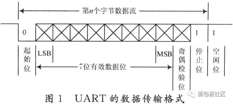 The meanings of each bit are as follows:
 Start Bit: A logical “0” signal is sent first to indicate the beginning of the transmission character;Data Bit: Can be 5 to 8 bits of logical “0” or “1”; for example, ASCII code (7 bits), extended BCD code (8 bits); little-endian transmission, meaning LSB is sent first, MSB last;Parity Bit: This bit, when added to the data bits, ensures that the number of “1” bits is even (even parity) or odd (odd parity);Stop Bit: This is the end marker of a character data. It can be 1 bit, 1.5 bits, or 2 bits of high level (used for synchronization between both parties; the longer the stop bit time interval, the stronger the error tolerance);Idle Bit: In a logical “1” state, indicating that there is no data transmission on the current line;

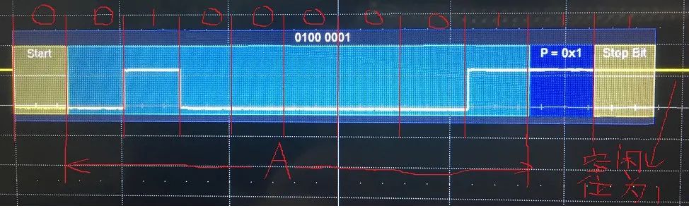
Baud Rate: This parameter is often confused with bit rate, but they are actually different. However, I believe the baud rate in UART can be considered as the bit rate, meaning the number of bits transmitted per second. Common baud rates include 9600, 19200, 115200, etc. This means that this number of bits is transmitted per second. Start Bit: A logical “0” signal is sent first to indicate the start of data transmission. Data Bit: The selectable values are 5, 6, 7, or 8, which can transmit this many bits of 0 or 1. This parameter is best set to 8 because if this value is set to something else when transmitting ASCII values, it will generally cause parsing issues. The reason is simple: an ASCII character value is 8 bits, and if a frame’s data bit is 7, then one bit will be an uncertain value, causing an error. Parity Bit: This bit, when added to the data bits, ensures that the number of “1” bits is even (even parity) or odd (odd parity) to verify the correctness of data transmission. For example, when transmitting “A” (01000001): 1. For odd parity: The 8 bits of the character “A” contain two 1s, so the parity bit should be 1 to satisfy the condition of having an odd number of 1s (odd parity). The waveform in Figure-1 illustrates this case. 2. For even parity: The 8 bits of the character “A” contain two 1s, so the parity bit should be 0 to satisfy the condition of having an even number of 1s (even parity). This bit can also be omitted, meaning the parity bit is not needed. Stop Bit: This is the end marker of a frame of data. It can be 1 bit, 1.5 bits, or 2 bits of idle level. You might find it strange that there can be 1.5 bits, but indeed there are. Therefore, when generating this UART signal, I use two waveform points to represent one bit. This does not need to be delved into… Idle Bit: The voltage level state on the line when there is no data transmission. It is at logic 1. Transmission Direction: Refers to whether the data is transmitted starting from the high bit (MSB) or from the low bit (LSB). For example, when transmitting “A”, if it is MSB, it is 01000001 (as shown in Figure-2), and if it is LSB, it is 10000010 (as shown in Figure-4). The order of data transmission in UART is as follows: first, a start bit is transmitted, followed by data bits, then the parity bit (if needed), and finally the stop bit. This completes the transmission of one frame of data. Then, this process continues. Additionally, I want to mention a parameter: Frame Interval: This is the size of the interval between frames of transmitted data, which can be measured in bits or time (knowing the baud rate allows conversion between bits and time). For example, after transmitting “A”, this is one frame of data, and when transmitting “B”, the interval between A and B is the frame interval.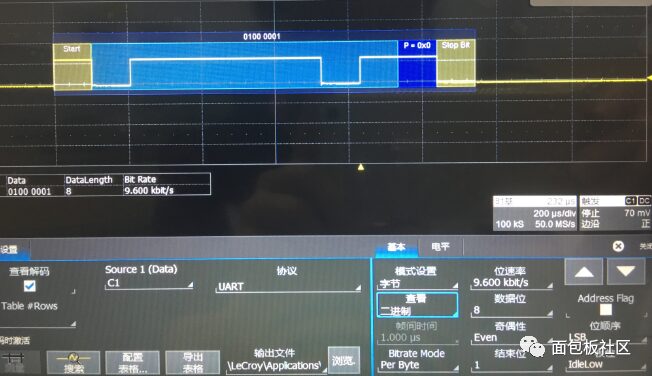 ↑ Figure-3
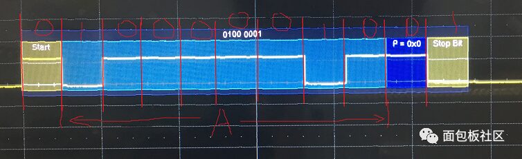 ↑ Figure-4
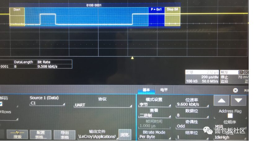
Disclaimer: The article is compiled from the internet, and the copyright belongs to the original author. If there are any copyright issues, please contact us promptly for deletion. Thank you!
For more technical content, click below to follow us
▽
-
Huawei Supply Chain Overview
-
Various Operating Modes of Electronic Loads
-
Current Detection Circuit
-
[Comic] Detailed Explanation of Power Supply
-
Basic Knowledge of Heat Dissipation Design
-
Comprehensive Introduction to USB Type-C Pin Signals and PCB Layout Wiring
-
Line Break Detection Circuit Making, Know Where It’s Broken at a Glance, Easy to Make
-
Relay Application Details
-
Detailed Explanation | Still Don’t Understand Serial Communication? Read This Article!
-
Making PCB Circuit Boards Using Thermal Transfer Method
-
What’s the Difference Between Transistors and MOSFETs? Should I Use MOSFETs or Transistors?
-
Comprehensive Capacitor Knowledge! All Here!
-
Analog Signal Acquisition from Hardware to Software, from Filtering to Actual Value Conversion, How Many Understand?
-
Summary: Conventional Amplifier Circuits and Differential Amplifier Circuits
-
TVS Diode Performance and Selection