1. What is the Validity of IIC Protocol Data?
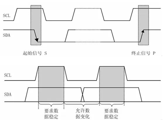
(1) Data Transmission Format Start and Stop Conditions: When the SCL line is high, a transition from high to low on the SDA line indicates a start condition; when SCL is high, a transition from low to high on the SDA line indicates a stop condition. Only the data transmitted between the start and stop conditions is considered valid. Data Bits: IIC transmits data in bytes, with an acknowledgment bit following each byte. The most significant bit (MSB) is transmitted first. After a complete byte is transmitted, the receiver will send an acknowledgment (ACK) or non-acknowledgment (NACK) to indicate whether the data was successfully received. If the receiver pulls the SDA line low during the 9th clock cycle, it is ACK, indicating the data is valid and received successfully; if the SDA line remains high, it is NACK, indicating the data is invalid or the reception failed. (2) Clock Synchronization SCL Signal: The SCL line is used to synchronize data transmission, and both the sender and receiver must sample and send data on the rising and falling edges of SCL. The receiver samples data on the SDA line during the high period of SCL; only if the SDA line remains stable during the high period of SCL is the sampled data considered valid. (3) Bus Idle State: The bus is in an idle state when there is no data transmission, with both SDA and SCL lines high. If other devices attempt to access the bus while it is busy, it can cause data conflicts, making the data invalid. Multi-Master Arbitration: When multiple master devices are on the bus, simultaneous data transmission may occur, and an arbitration mechanism is needed to determine which master device gains control of the bus.
During the arbitration process, master devices sending the same data will continue to compete, while those sending different data will determine whether they have lost arbitration based on the level state on the SDA line. The winning master device continues to transmit data, ensuring data validity.
2. What are the Three Signals of IIC?
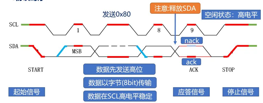
The three signals of the IIC protocol are the Start Signal, Data Signal, and Stop Signal. Here is a detailed introduction:
(1) Start Signal (START) Definition: When the SCL (clock line) remains high, a transition from high to low on the SDA (data line) is defined as the start signal, marking the beginning of an IIC communication. Function: It informs the slave devices on the bus that the master device is about to start sending data or commands, preparing for communication. When the slave devices detect the start signal, they will begin to listen for subsequent signals on the bus. (2) Data Signal Definition: After the start signal, the IIC bus begins to transmit data signals. Data is transmitted in bytes, each byte consisting of 8 data bits, starting with the most significant bit (MSB). After each byte transmission, an acknowledgment bit (ACK) is sent to confirm whether the data has been correctly received. Function: It is used for the master device to send data or commands to slave devices and for slave devices to return data to the master device. The master device conveys the data bits to be transmitted by placing the corresponding level state on the SDA line according to the rhythm of the clock signal SCL. (3) Stop Signal (STOP) Definition: When SCL remains high, a transition from low to high on the SDA line is defined as the stop signal, marking the end of an IIC communication. Function: It informs the devices on the bus that the communication has been completed, allowing slave devices to finish their operations, release relevant resources, or enter a standby state. After the master device sends the stop signal, it no longer occupies the bus resources, and the bus returns to an idle state.
3. What is the Data Transmission Process of the IIC Protocol?
(1) Initialization and Start Signal Bus Initialization: Before data transmission, the IIC bus must be in an idle state, with both SDA and SCL lines high. Sending the Start Signal: The master device keeps the SCL line high and pulls the SDA line from high to low, generating the start signal to notify the slave devices that communication is about to begin. (2) Address and Read/Write Bit Transmission Sending Device Address: After the start signal, the master device sends a 7-bit or 10-bit slave device address to determine which slave device to communicate with. Sending Read/Write Bit: The address bit is followed by a read/write bit, where ‘0’ indicates a write operation and ‘1’ indicates a read operation, informing the slave device of the master device’s intention. (3) Data Transmission and Acknowledgment Write Operation: The master device sends a data byte, and the slave device receives the data and sends an acknowledgment bit after each byte. If the slave device successfully receives the data, it will pull the SDA line low during the 9th clock cycle, indicating ACK; otherwise, it will keep SDA high, indicating NACK. Upon receiving NACK, the master device will take appropriate actions, such as resending data or terminating the transmission. Read Operation: After sending the read command, the slave device sends data bytes onto the bus, and the master device receives the data and sends an acknowledgment bit. If the master device needs more data after receiving the data, it sends ACK; if it has received all the required data, it sends NACK to inform the slave device to stop sending. (4) End of Data Transmission Sending Stop Signal: After completing data transmission, the master device keeps the SCL line high and pulls the SDA line from low to high, generating the stop signal to mark the end of communication, releasing bus resources and restoring the bus to an idle state. (5) Repeated Start Signal: In some cases, the master device may need to send a repeated start signal immediately after a communication ends without sending a stop signal, to communicate with the same or different slave devices, enabling continuous data read/write operations or communication with multiple slave devices.
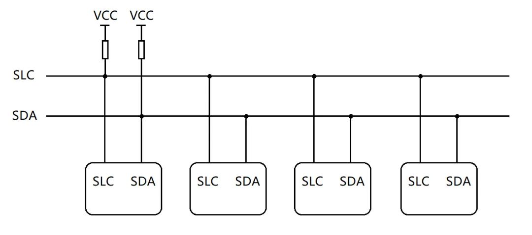
4. Why Does the IIC Protocol Require Pull-Up Resistors?

(1) Establish Default Levels
The IIC bus has an open-drain output structure, and without pull-up resistors, the level state of the SDA and SCL lines is uncertain. Pull-up resistors can pull the bus default high to a high level, ensuring that in the absence of data transmission or device output, the bus remains in a stable high level state, providing a clear starting and idle state reference for data transmission. (2) Implement Line and Function: Multiple devices on the IIC bus can share the SDA and SCL lines, achieving data transmission through wired logic. When one device pulls the bus low, other devices cannot pull it high; only when all devices release the bus, i.e., outputting in high-impedance state, can the bus return to high level under the action of pull-up resistors, enabling data exchange and arbitration among multiple devices. (3) Enhance Driving Capability: The output stage driving capability of devices on the IIC bus is limited, and pull-up resistors can provide additional driving current, ensuring that signal levels can be correctly transmitted and recognized, especially when multiple devices are connected on the bus or the bus length is long, reducing signal transmission attenuation and distortion, and improving signal integrity. (4) Suppress Noise Interference: Pull-up resistors can suppress noise interference to some extent. Without pull-up resistors, the bus is in a high-impedance state, making it susceptible to external interference and introducing noise. Pull-up resistors give the bus a definite level, enhancing its anti-interference capability and improving the stability and reliability of data transmission.
5. How Does the IIC Protocol Perform Read and Write Operations?
(1) Write Operation 1. Send Start Signal: The master device pulls the SDA line from high to low when SCL is high to generate a start signal, indicating the start of communication. 2. Send Slave Device Address and Write Bit: The master device sends a 7-bit or 10-bit slave device address, followed by a write bit (logic 0), informing the slave device on the bus that the master device intends to write data to it. 3. Wait for Slave Device Acknowledgment: After the slave device receives the address and write bit, if it recognizes its address, it will pull the SDA line low during the 9th clock cycle, sending an acknowledgment signal ACK to notify the master device that it is ready to receive data. 4. Send Data Byte: The master device begins sending data, starting with the most significant bit (MSB). After sending each data byte, the master device will wait for the slave device’s acknowledgment during the 9th clock cycle. 5. Repeat Sending Data: If multiple bytes of data need to be sent, the master device will repeat the previous step, sending each byte one by one, waiting for the slave device’s acknowledgment for each byte. 6. Send Stop Signal: After the data has been sent, the master device pulls the SDA line from low to high when SCL is high, generating a stop signal to end the write operation. (2) Read Operation 1. Send Start Signal: The same start signal as in the write operation, where the master device pulls the SDA line from high to low when SCL is high to initiate communication. 2. Send Slave Device Address and Read Bit: The master device sends the slave device address, followed by a read bit (logic 1), indicating that it wants to read data from the slave device. 3. Wait for Slave Device Acknowledgment: After the slave device recognizes the address and read bit, if it matches its own address, it will send an ACK acknowledgment, preparing to send data. 4. Receive Data Byte: The slave device begins sending data through the SDA line, and the master device samples the data on SDA during each clock cycle of SCL, starting with the most significant bit. After receiving a byte, the master device must send an acknowledgment signal to the slave device. 5. Determine Whether to Continue Reading: If the master device still needs to read more data, it sends ACK, and the slave device will continue to send the next byte of data; if the master device has finished reading the required data, it sends NACK to inform the slave device to stop sending data. 6. Send Stop Signal: After the master device has received the data, it sends a stop signal to release the bus and end the read operation.