The PLC and the inverter have a relationship of inclusion and being included. Both can execute specific commands to control electric motors. The PLC is a hardware device for program input execution, while the inverter is one of them.
However, the scope of the PLC is broader than that of the inverter, as it can control more devices, has a wider range of applications, and is more powerful. Naturally, the control precision of the PLC is also greater. The inverter cannot be programmed; it changes parameters such as frequency and voltage of the power supply, with its output frequency set to a fixed value or dynamically controlled by the PLC.
The PLC can be programmed to control electrical components or complete tasks such as functionality and communication.
Communication between the PLC and the inverter needs to follow the Universal Serial Bus Protocol (USS), determining access methods according to the master-slave communication principle of the serial bus. A master station can connect to up to 31 slave stations on the bus, and the master selects which slave to transmit data to based on the address character in the communication message. The slave cannot send data first unless requested by the master, and the slaves cannot directly transmit information among themselves.
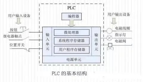
The programmable controller’s memory can be divided into three types: system program memory, user program memory, and working data memory.
1. System Program Memory
This memory stores the system programs written by the programmable controller manufacturer, which are fixed in ROM and cannot be directly changed by users. The quality of the system program largely determines the performance of the PLC.
It mainly includes three parts: the first part is the system management program, which controls the operation of the programmable controller, ensuring that the entire system operates in an orderly manner; the second part is the user instruction interpretation program, which converts the programming language of the programmable controller into machine language instructions for execution by the CPU; the third part consists of standard program modules and system call programs.
2. User Program Memory
The application program compiled according to control requirements is called the user program. User program memory stores various user programs written in the specified programming language for specific control tasks.
Currently, advanced programmable controllers use flash memory as user program memory, which does not require a backup battery and does not lose data when power is off.
3. Working Data Memory
This memory is used to store working data, i.e., the ON/OFF states, numerical data, etc., used in user programs. The working data area includes component image registers and data tables. The component image register stores the ON/OFF states of switches, output states, timers, counters, and auxiliary relays. The data table stores various data, including variable parameter values during the execution of user programs and digital quantities and results obtained from A/D conversions.
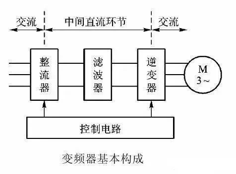
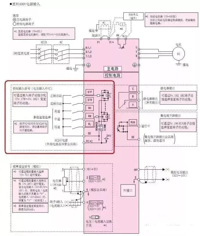
The inverter converts the industrial frequency power supply (50Hz or 60Hz) into various frequencies of AC power, enabling variable speed operation of the motor. The control circuit completes the control of the main circuit; the rectifier circuit converts AC power into DC power; the DC intermediate circuit smooths the output of the rectifier circuit; the inverter circuit converts DC power back into AC power. For inverters requiring significant calculations, such as vector control inverters, a CPU for torque calculations and some corresponding circuits may also be necessary.
① Using the PLC’s Analog Output Module to Control the Inverter: The PLC’s analog output module outputs a voltage signal of 0–5V or a current signal of 4–20mA as the analog input signal for the inverter, controlling the inverter’s output frequency. This control method has a simple wiring setup but requires selecting a PLC output module that matches the inverter’s input impedance, and the PLC’s analog output module can be relatively expensive. Additionally, voltage division measures must be taken to ensure the inverter can adapt to the PLC’s voltage signal range, and care should be taken to separate wiring to prevent noise from the main circuit side from affecting the control circuit.
② Using the PLC’s Switch Output to Control the Inverter: The PLC’s switch output can generally be directly connected to the inverter’s switch input terminal. This control method is simple in wiring and has strong anti-interference capability. Using the PLC’s switch output can control the inverter’s start/stop, forward/reverse, jog, speed, and acceleration/deceleration time, achieving relatively complex control requirements but only allowing step speed regulation.
When using relay contacts for connection, there may be misoperation due to poor contact. When using transistors for connection, considerations must be made regarding the voltage and current capacity of the transistors to ensure system reliability. Additionally, when designing the input signal circuit of the inverter, improper connections can sometimes cause misoperation of the inverter. For example, when using inductive loads like relays in the input signal circuit, the surge current generated when the relay opens and closes may introduce noise that causes misoperation of the inverter, so it should be avoided.
③ Connection of PLC with RS-485 Communication Interface: All standard Siemens inverters have an RS-485 serial interface (some also provide RS-232 interfaces), using a two-wire connection, designed for industrial environmental applications. A single RS-485 link can connect up to 30 inverters, and based on the addresses of each inverter or by using broadcast messages, the required inverter can be found. The link requires a master controller (master station), while the inverters are subordinate control objects (slave stations).
1. After connecting the wires according to the wiring diagram, start the power supply and prepare to set the various parameters of the inverter.
2. Press the “MODE” key to enter the parameter setting mode, set Pr.79 to “2”: external operation mode, with the start signal input from external terminals (STF, STR), and speed adjustment input from external terminals (between 2 and 5, between 4 and 5, multi-speed).
3. Continuously press the “MODE” button to exit the parameter setting mode.
4. Press the forward button to start the motor in the forward direction.
5. Press the stop button to stop the motor.
6. Press the reverse button to start the motor in the reverse direction.
7. Press the stop button to stop the motor.
8. If the reverse button is pressed while the motor is running forward, the motor will stop first and then reverse; conversely, if the forward button is pressed while the motor is running in reverse, the motor will stop first and then run forward.
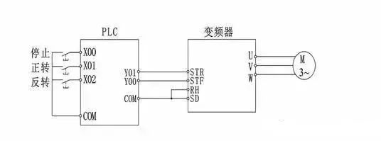
1. PLC Switch Signal Controls the Inverter
The output points and COM points of the PLC (MR type or MT type) are directly connected to the inverter’s STF (forward start), RH (high speed), RM (medium speed), RL (low speed), and input terminal SG. The PLC can control the inverter’s start, stop, and reset through programming; it can also control different combinations of the inverter’s high-speed, medium-speed, and low-speed terminals to achieve multi-segment speed operation. However, since it uses switch signals for control, the speed regulation curve is not a continuous smooth curve, and fine speed adjustment cannot be achieved.
2. PLC Analog Signal Controls the Inverter
Hardware: FX1N type, FX2N type PLC main unit, configured with a simple FX1N-1DA-BD expansion analog output board; or mixed analog input/output module FX0N-3A; or two-output FX2N-2DA; or four-output FX2N-4DA module, etc. Advantages: PLC programming is simple and convenient, the speed regulation curve is smooth and continuous, and the operation is stable.
Disadvantages: In large-scale production lines, long control cables, especially when the DA module uses voltage signal output, can experience significant voltage drops, affecting the stability and reliability of the system.
3. PLC Uses RS-485 Communication Method to Control the Inverter
This is the most commonly used method, where the PLC uses RS serial communication commands for programming. Advantages: simple hardware, lowest cost, can control 32 inverters. Disadvantages: large programming workload.
4. PLC Uses RS-485 Modbus-RTU Communication Method to Control the Inverter
The new Mitsubishi F700 series inverter uses the RS-485 terminal to communicate with the PLC using the Modbus-RTU protocol. Advantages: PLC programming using Modbus communication is simpler and more convenient than the RS-485 unprotocol method. Disadvantages: the programming workload is still large.
5. PLC Uses Fieldbus Method to Control the Inverter
The Mitsubishi inverter can be equipped with various types of communication options, such as the FR-A5NC option for CC-Link fieldbus; the FR-A5AP (A) option for Profibus DP fieldbus; the FR-A5ND option for DeviceNet fieldbus, etc. Mitsubishi FX series PLC has corresponding communication interface modules to connect.
Advantages: fast speed, long distance, high efficiency, stable operation, simple programming, and can connect many inverters. Disadvantages: relatively high cost.
6. Use of Extended Memory
Advantages: low cost, easy to learn and use, reliable performance. Disadvantages: can only be used in systems with no more than 8 inverters.
Without external controllers (like PLCs), there are three ways to directly operate the inverter:
① By using the buttons on the operation panel;
② By connecting components (like buttons and potentiometers) to the operation terminals;
③ Composite operation (such as setting frequency on the operation panel and using buttons connected to the terminals for start/stop control). For convenience and to fully utilize the inverter, PLC can also be used to control the inverter.
There are three basic ways for PLC to control the inverter:
① By using switch signals;
② By using analog signals;
③ By using RS485 communication.
The inverter has many switch terminals, such as forward, reverse, and multi-speed control terminals. When not using a PLC, simply connecting switches to these terminals can control the inverter’s forward, reverse, and multi-speed control. When using a PLC to control the inverter with switch signals, the switch output terminals of the PLC need to be connected to the switch input terminals of the inverter. To detect certain states of the inverter, the switch output terminals of the inverter can also be connected to the switch input terminals of the PLC.
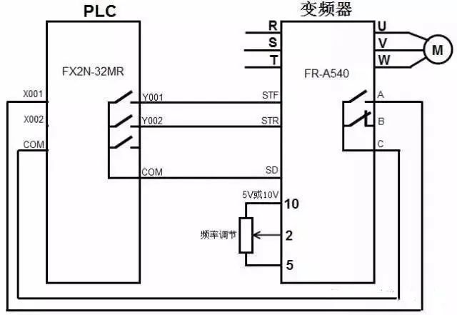
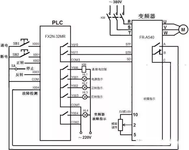
The hardware connection for controlling the inverter with switch signals via PLC is shown in the following diagram. When the internal program of the PLC runs and the Y001 terminal’s internal contact closes, it is equivalent to closing the external switch of the inverter’s STF terminal, making the STF terminal input ON, which starts the motor in the forward direction. Adjusting the potentiometer connected to terminals 10, 2, and 5 can change the input voltage of terminal 2, thus changing the output frequency of the inverter and altering the motor speed. If an internal anomaly occurs in the inverter, the internal contacts between terminals A and C close, which is equivalent to closing the external switch of the PLC’s X001 terminal, making the X001 terminal input ON.
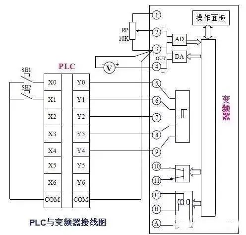
The inverter has some voltage and current analog input terminals. Changing the voltage or current input values of these terminals can alter the motor speed. If these terminals are connected to the PLC’s analog output terminals, the PLC can control the inverter to adjust the motor speed. Analog signals are continuously variable, and using analog control allows for smooth and continuous speed changes (infinitely variable speed).
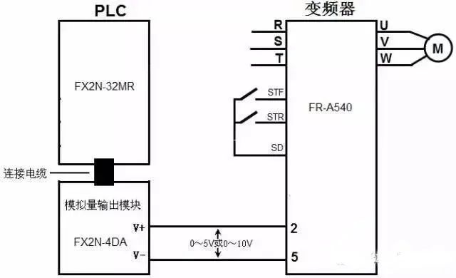
The hardware connection for controlling the inverter with analog signals via PLC is shown in the following diagram. Since the Mitsubishi FX2N-32MR PLC lacks analog output functionality, it needs to connect to an analog output module (like FX2N-4DA), then connect the output terminals of the analog output module to the inverter’s analog input terminals. When the external switch of the inverter’s STF terminal closes, that terminal input is ON, and the inverter starts the motor in the forward direction. The digital data generated by the internal program of the PLC is sent to the analog output module (DA module) via connecting cables, which converts it into a voltage (analog signal) in the range of 0–5V or 0–10V sent to the inverter’s terminals 2 and 5, controlling the output frequency of the inverter and thus controlling the motor speed. If the voltage output from the DA module to the inverter’s terminals 2 and 5 changes, the inverter’s output frequency will also change, thereby altering the motor speed.
When the PLC uses analog signals to control the inverter’s analog input terminals, it can also simultaneously use switch signals to control the inverter’s switch input terminals.
When PLC controls the inverter with switch signals, it occupies many output terminals to connect to the corresponding input terminals of the inverter to control functions like forward, reverse, and stop. When PLC controls the inverter with analog signals, it requires a DA module for frequency speed control. If PLC controls the inverter using RS485 communication, only one RS485 communication cable (containing 5 core wires) is needed to directly send various control and frequency adjustment commands to the inverter. The inverter executes the corresponding functional control based on the commands sent by the PLC through the RS485 communication cable.
RS485 communication is a widely used communication method in industrial control, with strong anti-interference capability, and communication distances ranging from tens of meters to over a thousand meters. RS485 communication not only connects two devices for communication but can also connect multiple devices (up to 32 devices in parallel) to form a distributed system for mutual communication.
1. RS485 Communication Port of Inverter
The Mitsubishi FR500 series inverter has a PU port for connecting the operation panel, which can also be used as an RS485 communication port. When using RS485 communication with other devices, the operation panel plug (RJ45 plug) must be removed from the PU port, and one end of the RS485 communication cable should be inserted into the PU port, while the other end connects to the PLC or other devices. The appearance and functional description of the FR500 series inverter PU port are shown in the following diagram.
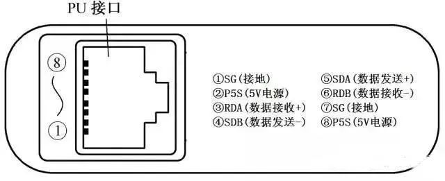
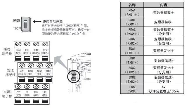
The Mitsubishi FR500 series inverter has only one RS485 communication port (PU port), and panel operation and RS485 communication cannot be performed simultaneously. In contrast, the Mitsubishi FR700 series inverter has a separate RS485 communication port (terminal block) in addition to the PU interface, exclusively for RS485 communication. The appearance and functional description of the RS485 communication port of the Mitsubishi FR700 series inverter are shown in the following diagram, where each functional terminal of the communication port has two terminals, one connected to one RS485 communication device and the other terminal connected to the next RS485 communication device. If there is no next device, the terminal resistor switch should be set to the “100Ω” side.
2. RS485 Communication Port of PLC
The Mitsubishi FX PLC generally does not come with an RS485 communication port. If it needs to communicate with the inverter via RS485, the FX2N-485BD communication board must be installed on the PLC. The appearance and terminals of the 485BD communication board are shown in the following diagram (a), and the installation method is shown in the following diagram (b).

(a) Appearance
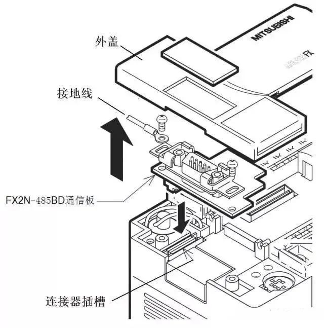
(b) Installation Method
3. RS485 Communication Connection between Inverter and PLC
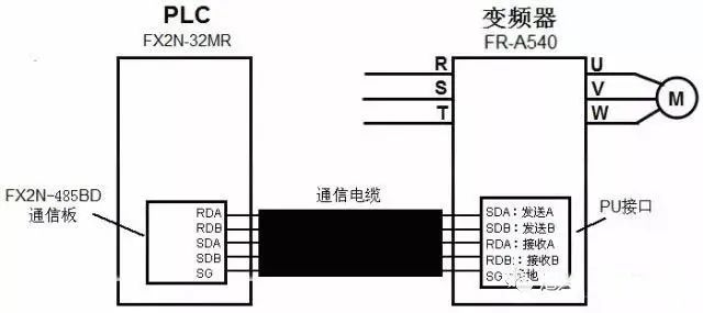
(1) RS485 Communication Connection of a Single Inverter and PLC
The RS485 communication connection of a single inverter and PLC is shown in the following diagram. When connecting, the sending terminal (+/-) of one device should be connected to the receiving terminal (+/-) of the other device, and the receiving terminal (+/-) should be connected to the sending terminal (+/-) of the other device.
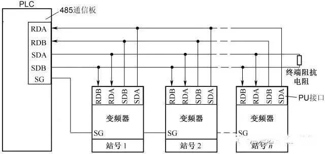
(2) RS485 Communication Connection of Multiple Inverters and PLC
The RS485 communication connection of multiple inverters and PLC is shown in the following diagram, allowing one PLC to control the operation of multiple inverters.
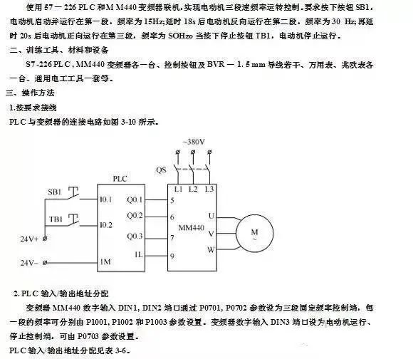
1. Wiring Diagram for PLC and Inverter Connection
The wiring diagram for PLC controlling the inverter to drive the motor forward and reverse using switch signals is shown in the following diagram.
2. Parameter Settings for the Inverter
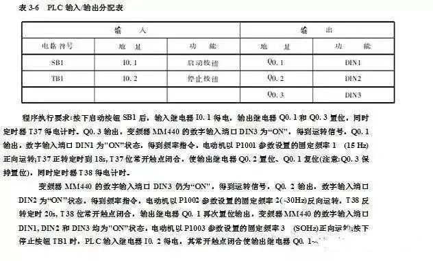
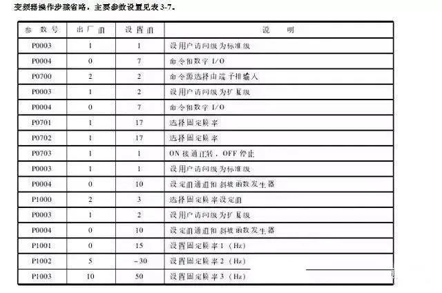
When using PLC to control the inverter, relevant parameter settings for the inverter are required, as detailed in the following table.
3. Writing the PLC Control Program
After the relevant parameters of the inverter are set, the corresponding PLC control program must also be written using programming software and downloaded to the PLC. The PLC program for controlling the inverter to drive the motor forward and reverse is shown in the following diagram.
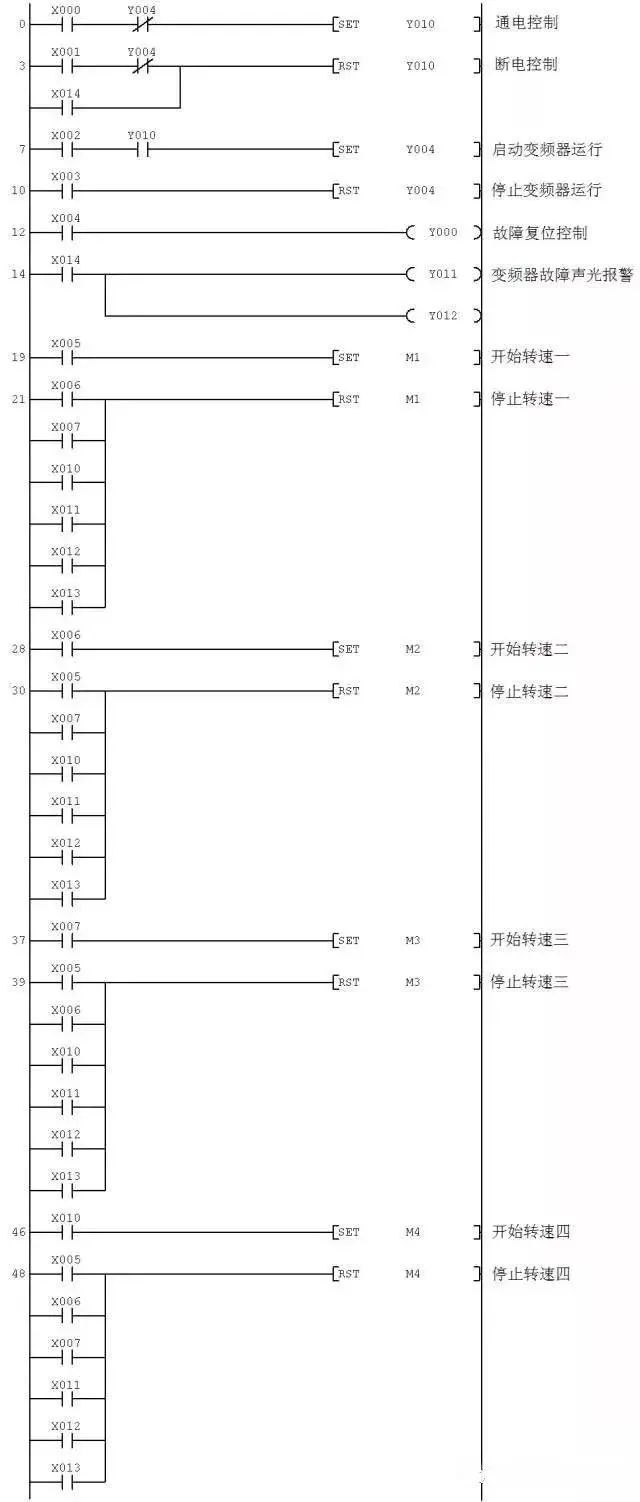
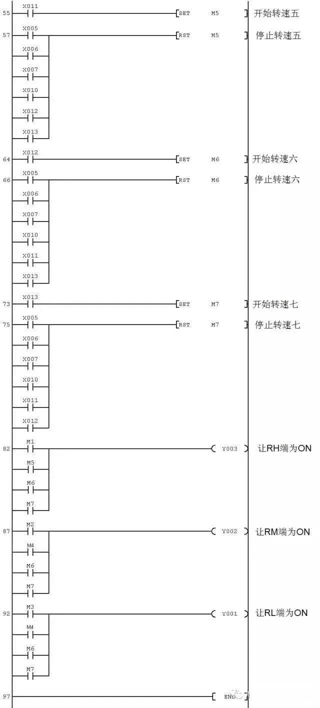
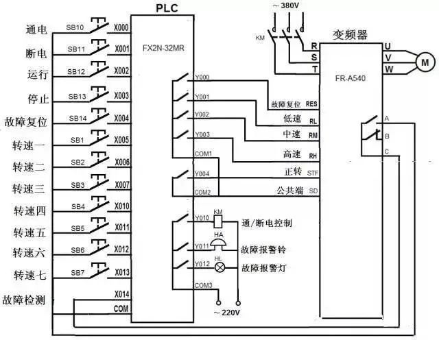
The inverter can operate with continuous speed adjustment or segmented speed adjustment. The FR-500 series inverter has three control terminals: RH (high speed), RM (medium speed), and RL (low speed). By combining these three terminals, seven-speed control can be achieved. If the PLC’s output terminals are connected to these terminals of the inverter, the PLC can control the inverter to drive the motor with multi-speed operation.
1. Wiring Diagram for PLC and Inverter Connection
The wiring diagram for PLC controlling the inverter to drive the motor with multi-speed operation using switch signals is shown in the following diagram.
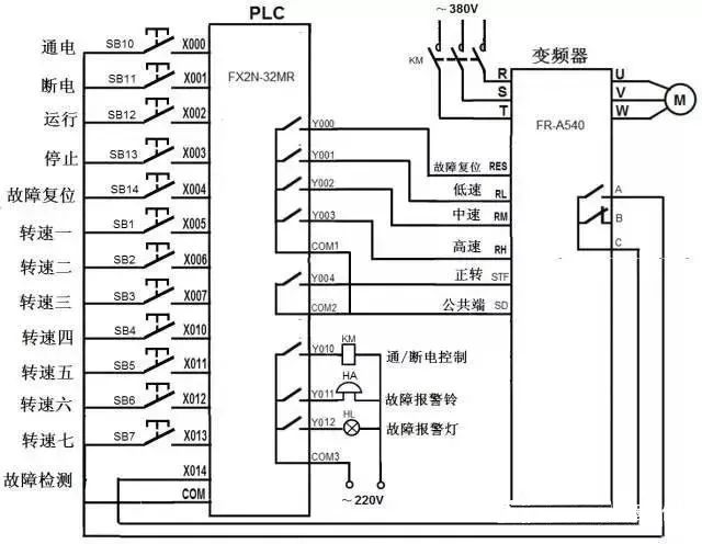
2. Writing the PLC Control Program
The PLC program for controlling the inverter to drive the motor with multi-speed operation using switch signals is shown in the following diagram.