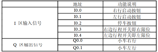
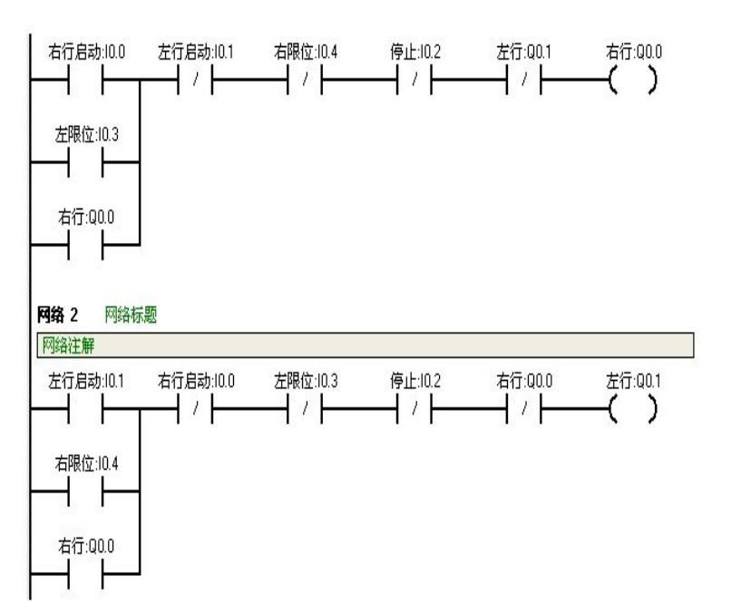
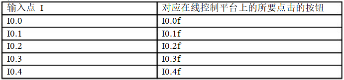
Use S7-200 to achieve automatic control of the cart’s bidirectional movement. The control process is as follows: press the start button, and the cart moves from the left to the right (and vice versa). When it reaches the right (or left) limit switch, the cart automatically returns. It continues this back-and-forth motion until the stop button is pressed.
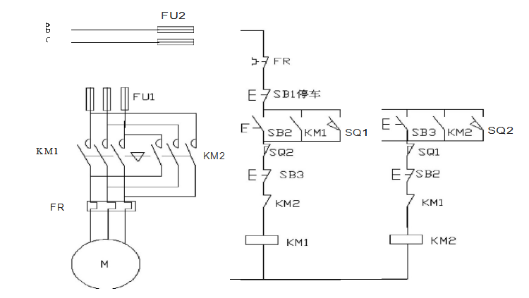
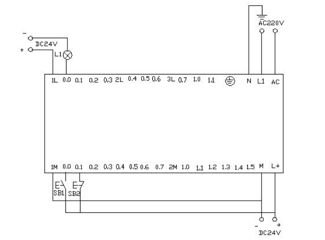
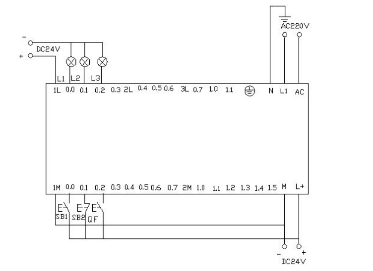
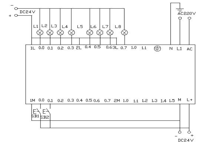
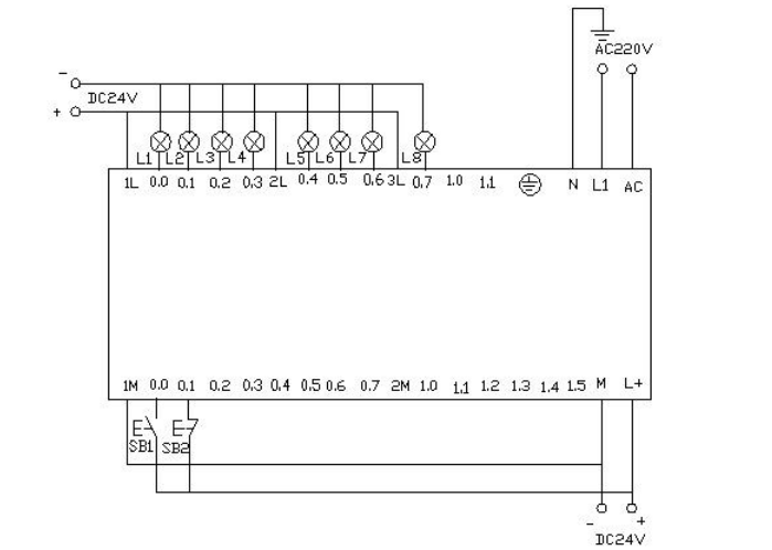
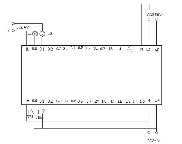
▲ Electrical Wiring Diagram
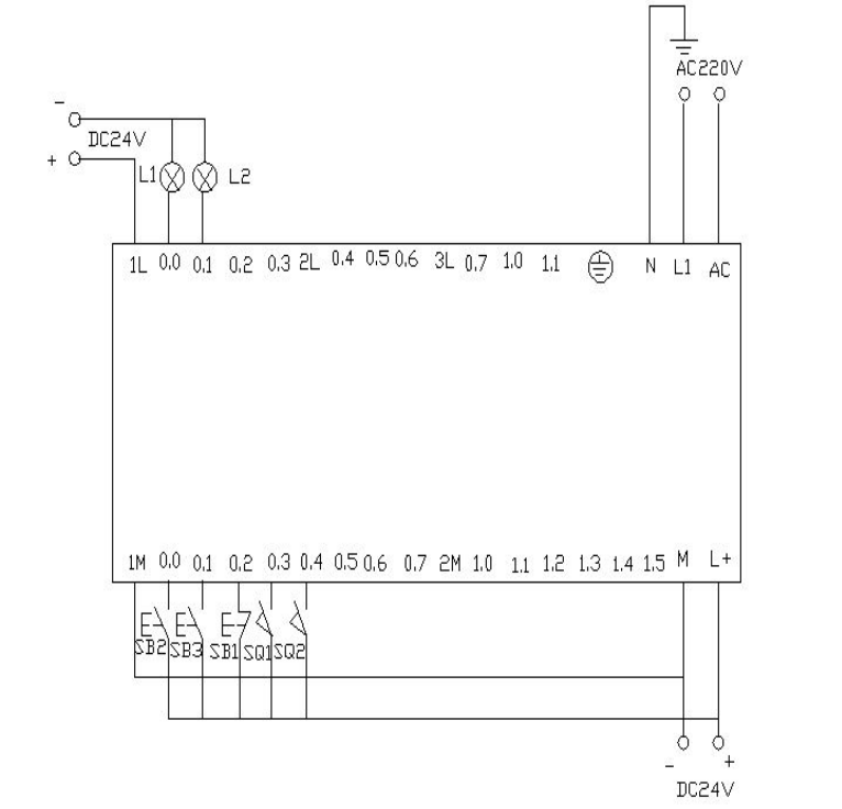
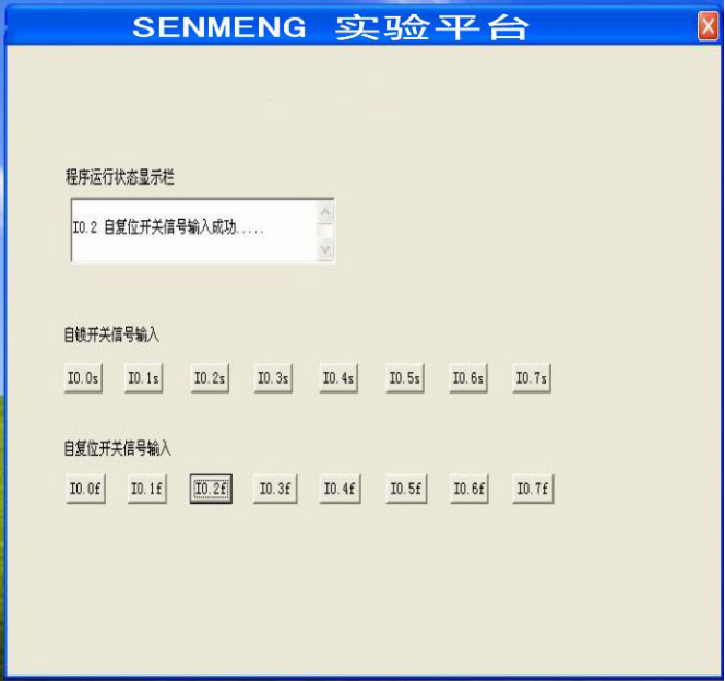
▲ Control Platform Operation Panel
When SB2 is pressed, i0.0 (mouse click i0.0f) is activated, Q0.0 is activated, and the cart moves to the right (indicated by the light Q0.0 being on). When the cart touches the right limit switch SQ2 (i0.4) (simulating SQ2 being pressed with mouse click i0.4f), it moves to the left (Q0.0 light goes off, Q0.1 light goes on). When it reaches the left limit switch SQ1 (i0.3), it moves back to the right (Q0.1 light goes off, Q0.0 light goes on). This back-and-forth continues until SB1 (i0.2) is pressed, stopping the cart.
Appendix:
When the start button is pressed, the light should flash once every second for two seconds, repeating this cycle.
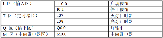
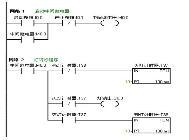
Download the written program to the Siemens S7-200 PLC for debugging. Observe whether the running results match the experimental requirements. Debug through the online control panel. When I0.0f (i0.0 is activated) is pressed, Q0.0 outputs, and the connected load light turns on. Timer T37 starts timing after one second. When T37 acts, its normally closed contact opens, so Q0.0 outputs nothing, and the connected load light goes off. At this time, timer T38 starts timing. After one second, the normally closed contact in series with T37 opens, resetting T37, and its normally closed contact returns to normal. At this point, Q0.0 outputs again, and the connected load light turns on. Thus, the output Q0.0 connected load light flashes on and off every second until I0.1f (i0.1 is activated) is pressed, stopping the flashing circuit. If you want to change the flashing frequency of the light, just change the timer’s time to achieve the desired change.
Use Siemens S7-200 PLC to achieve star-delta soft start wiring.
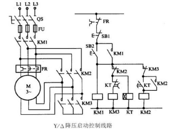
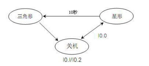
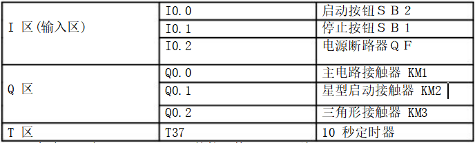
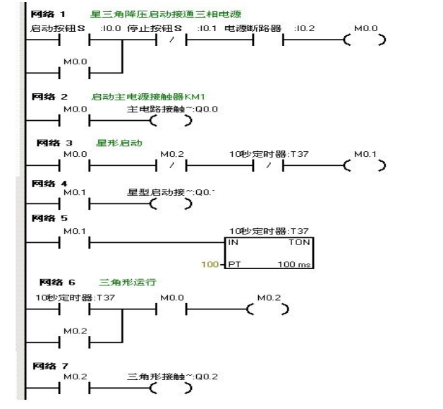
Download the written program to the Siemens S7-200 PLC for debugging. After downloading, we open the online control panel for debugging to see if the running results meet the requirements. First, set i0.2f on the control panel as the button pressed, indicating the circuit breaker QF is closed. Press the start button i0.0f (SB2) to activate i0.0, indicating the motor starts in star mode. Q0.0 and Q0.1 output, as indicated by the lights L1 and L2 being on, simultaneously driving the timer. When the timer counts to 10 seconds, it switches to delta mode, at which point Q0.1 outputs nothing, and Q0.2 outputs, meaning Q0.0 and Q0.2 output, and the motor runs in delta mode. The lights L1 and L3 are on. When i0.1f on the online panel is pressed (i0.1 is activated), the motor stops running, and all output points are off.
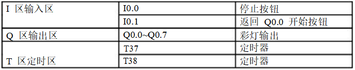
Use PLC’s Q0.0 to Q0.7 eight output terminals to control eight color lights, making each light turn on one by one every second in a loop. When I0.0 is activated, all lights go out. When I0.1 is activated, the cycle starts again from Q0.0.
Download the written program to the PLC for debugging. After downloading, we open the online control panel for debugging to see if the running results meet the requirements.
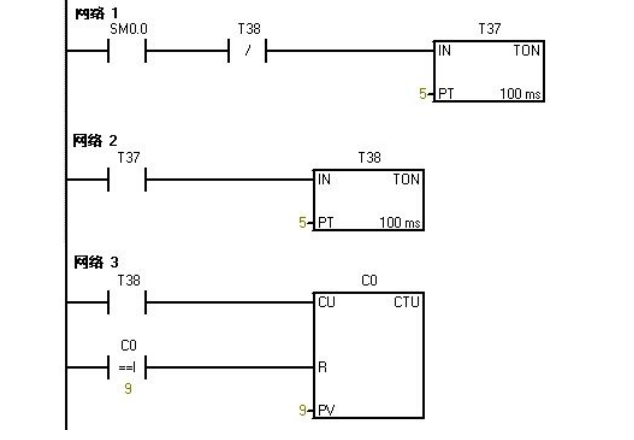
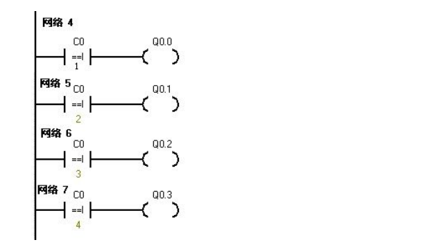
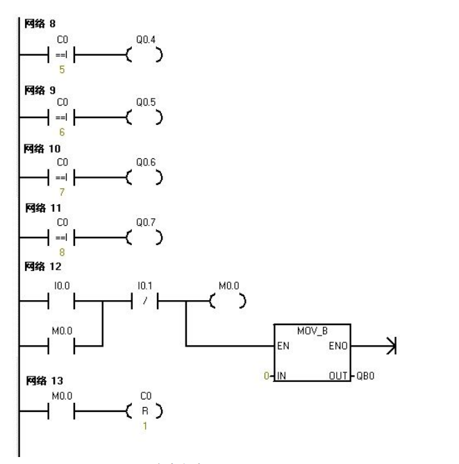
Once the PLC is powered on, SM0.0 remains activated. Thus, T37 starts timing. After timing is complete, T38 starts timing. Once T38 times out, its normally closed contact opens, causing T37 to stop timing, and T37’s normally open contact returns to normal, causing T38 to also stop timing. At this point, T38’s normally closed contact returns to normal, and T37 starts timing again, while counter C0 begins counting once. This counting repeats. When the count is 1, Q0.0 is activated. When the counter reaches 2, Q0.1 is activated… This continues until the counter reaches 8, at which point Q0.7 is activated. When the counter reaches 9, the counter C0 resets. When I0.0f (i0.0) is pressed, the counter and Q0.0~Q0.7 all reset, meaning no lights are on. When I0.1f (i0.1) is pressed, the counter starts counting again, and the lights start lighting up one by one from Q0.0.
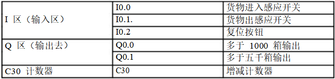
Record the goods entering and leaving the warehouse. The warehouse can hold a maximum of 6000 boxes of goods. If there are more than 1000 boxes, the light L1 turns on; if there are more than 5000 boxes, the light L2 turns on.
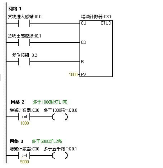
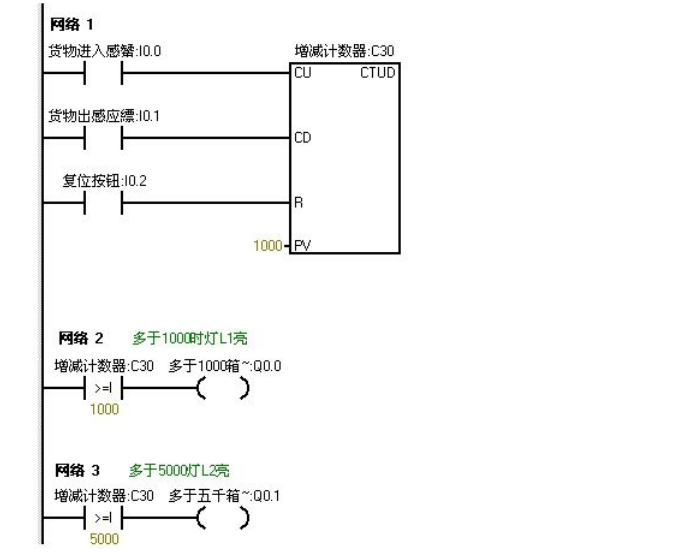
Download the program to the S7-200 PLC for debugging. Before downloading, we first reduce the numbers in the program to better observe the experimental results. We set the light L1 to turn on at 5 and light L2 to turn on at 10. This allows us to see the experimental results more quickly.
When I0.0f on the online control panel is pressed, indicating that goods are entering, and after clicking I0.0f five times, the counter’s count is 5 (indicating 1000 boxes of goods in the warehouse), thus light L1 should turn on, meaning Q0.0 outputs. After clicking I0.0f ten times, the counter’s count is 10 (indicating 5000 boxes of goods in the warehouse), thus light L2 also turns on, meaning Q0.1 outputs. Continuing to click I0.0f increases the counter’s count. When I0.1f is pressed, the counter starts decreasing. Each click decreases the counter’s count by one. When the counter’s value is less than 10, indicating there are less than 5000 boxes in the warehouse, light L2 turns off (Q0.1 outputs nothing). Continuing to click I0.1f decreases the counter’s value further. When it decreases below 5, indicating less than 1000 boxes in the warehouse, light L1 turns off (Q0.0 outputs nothing). When I0.2f is pressed, the counter resets, and both L1 and L2 turn off (Q0.0 and Q0.1 output nothing).
Use IO wires to control the eight color lights connected to Q0.0 to Q0.7 to shift in a loop, using T37 for timing, shifting every 0.5 seconds. During the first scan, set initial values for Q0.0 to Q0.7, allowing Q0.0 and Q0.2 to output first. Use I0.1 to control the direction of the color light shift.
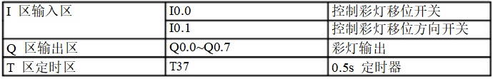
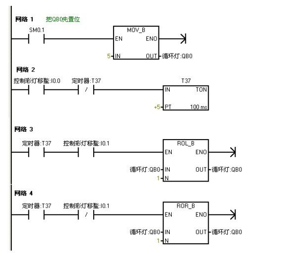
Download the program to the Siemens S7-200 PLC for debugging. When the PLC is powered on, Q0.0 and Q0.2 output, thus lighting up Q0.0 and Q0.2. When the online panel’s I0.0f (indicating I0.0 has input) switch is pressed, timer T37 starts timing, shifting the color lights based on Q0.0 and Q0.2 to the right every 0.5 seconds. When the online control panel’s I0.1f (indicating I0.1 has input) switch is pressed, the color lights shift to the left in the same manner.
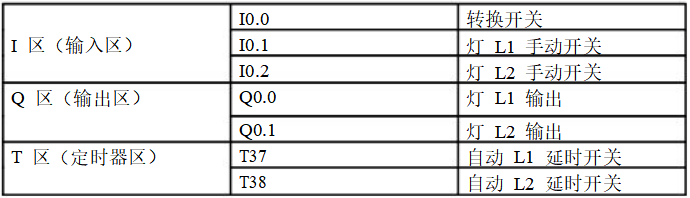
Use jump instructions to control two lights L1 and L2, connected to Q0.0 and Q0.1, with the switch I0.0, and the control switches for the two lights I0.1 and I0.2. In manual mode, use the two light control switches separately. In automatic mode, the two lights alternate every second.
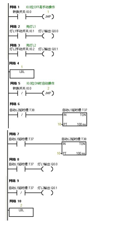
Download the written program to the S7-200 PLC for debugging. When I0.0 is OFF, the PLC runs the manual program. Press the online control panel’s set button I0.1f and I0.2f, indicating (I0.1 and I0.2 are closed), lights L1 and L2 turn on, meaning Q0.0 and Q0.1 output. When the online control panel’s I0.0f is pressed, I0.0 turns ON, and the program jumps to run the automatic program. The two lights alternate every second, first L1 for one second, then L2. When I0.0f is pressed again, I0.0 turns OFF, and the program jumps back to run the manual program.
▲ Program monitoring diagram when PLC is powered on, blue indicates activated
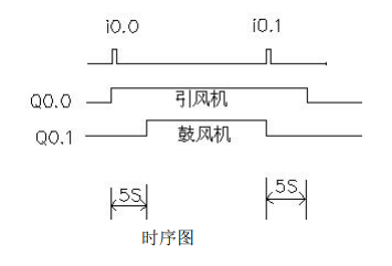
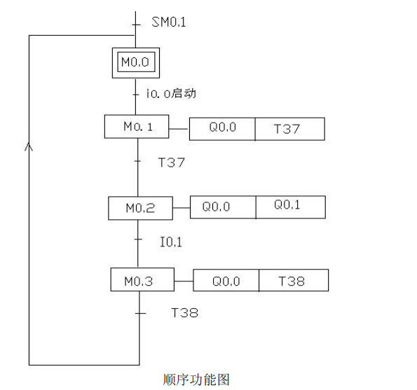
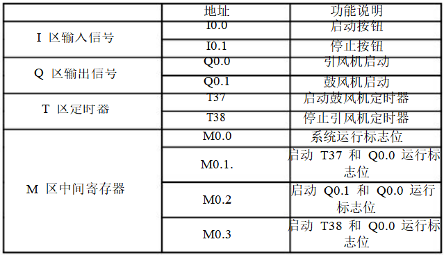
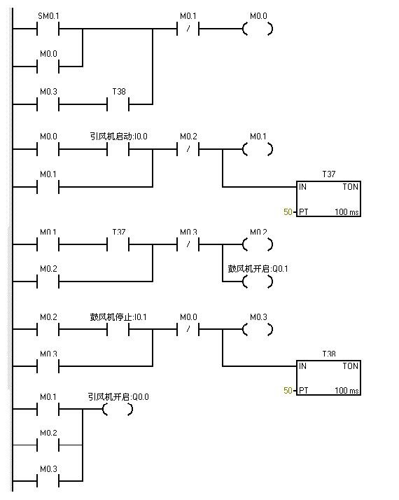
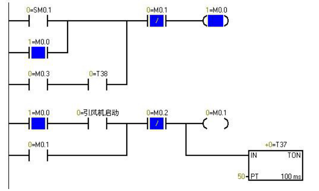
SM0.1 is activated in the first scanning cycle and remains activated afterward. When the online control panel’s I0.0f is pressed (i0.0 is activated), Q0.0 is activated (indicating light Q0.0 is on), and the inducer starts. Timer T37 is activated and starts timing. When the timer counts to 50 (indicating light Q0.1 is on), the blower starts. Both fans run. When I0.1f is pressed (i0.1 is activated), the blower stops (indicating light Q0.1 goes off), while timer T38 is activated and starts timing. After 5 seconds, the inducer stops (indicating light Q0.0 goes off).
Use S7-200 to achieve automatic control of liquid mixing. When the start button is pressed, valve A opens, and liquid A flows into the mixer. When the liquid level reaches the middle limit, valve A closes, and valve B opens, allowing liquid B to flow into the mixer. When the liquid level reaches the upper limit, valve B closes, and the motor starts mixing. After one minute, the motor stops, and valve C opens, allowing the mixed liquid to flow out. When the liquid level reaches the lower limit, after 5 seconds, the container empties, and valve C closes. Valve A opens again to inject liquid A. This cycle continues. If the stop button is pressed, the system must wait for one complete cycle to finish before stopping.
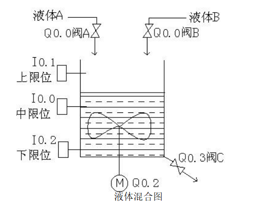
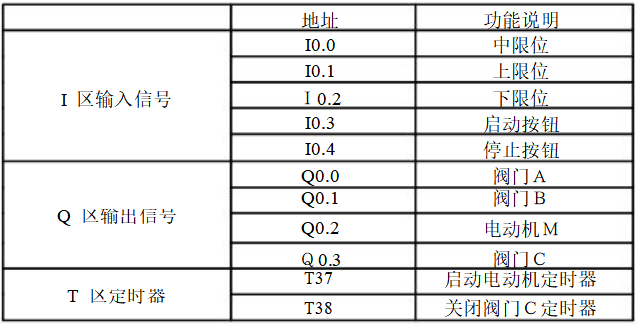
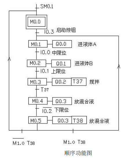
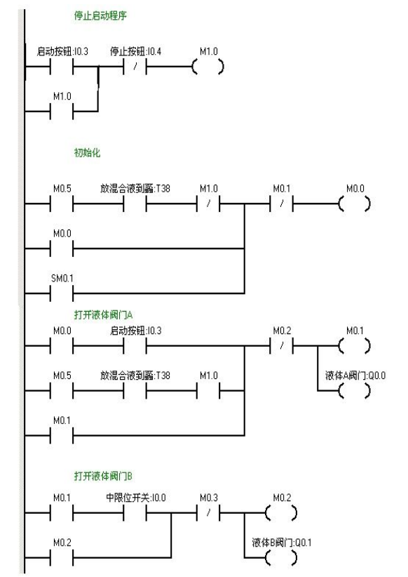
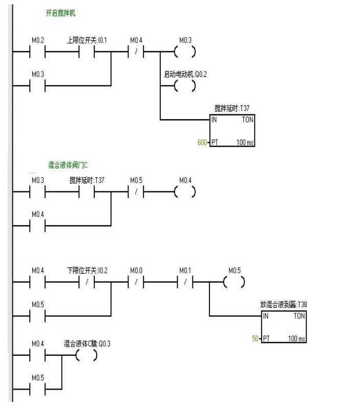
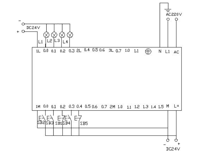
When I0.03f (i0.3 is closed) is pressed, valve A opens (indicating Q0.0 is on). When I0.0f (indicating I0.0 middle limit is closed) is pressed, valve A closes, and valve B opens (indicating Q0.0 goes off, Q0.1 lights up). When I0.1f (indicating upper limit I0.1 is closed) is pressed, valve B closes, and the motor starts mixing (indicating Q0.1 goes off, Q0.2 lights up), while timer T37 starts timing for one minute. After one minute, the mixer stops mixing, and valve C opens (indicating Q0.2 goes off, Q0.3 lights up). When the liquid level reaches the lower limit, valve C continues to open (indicating Q0.3 lights up), and timer T38 starts timing. After 5 seconds, valve C closes and valve A opens (indicating Q0.3 goes off, Q0.0 lights up), entering the next cycle. Pressing I0.4f (indicating stop I0.4 is closed) does not immediately stop the system but waits until one cycle is completed before stopping.
Disclaimer: This article is reprinted from the internet, and the copyright belongs to the original author. If there are copyright issues, please contact us to delete it in a timely manner. Thank you!
Complete question bank for the 2021 Electrician Primary Exam (includes answers)
Three must-have tools for electricians, easily accessible with WeChat!
【Collection】 The “path” of a ten-year veteran electrician, secrets to earning over ten thousand a month!
Which of the five major electrical drawing software (CAD, Eplan, CADe_simu…) do you pick?
Latest electrical CAD drawing software, with a super detailed installation tutorial!
Latest electrical drawing software EPLAN, with a super detailed installation tutorial!
Common issues for beginners using S7-200 SMART programming software (includes download link)
Comprehensive electrical calculation EXCEL sheet, automatically generated! No need to ask for electrical calculations!
Bluetooth headsets, electrician/PLC beginner books available for free? Come and claim your electrical gifts!
Basic skills of PLC programming: Ladder diagrams and control circuits (includes 1164 practical cases of Mitsubishi PLC)
Still can’t understand electrical diagrams? Basic electrical diagram recognition, simulation software available for you to quickly grasp theory and practice!
12 free electrician video courses, 10GB software/e-books, and 30 days of free electrician live courses are being given away!