
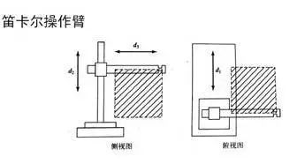
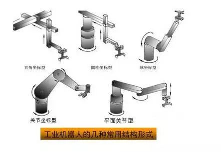
 1. Common Kinematic Configurations1. Cartesian ManipulatorAdvantages: Easily controlled by computers, achieving high precision. Disadvantages: Obstructs work, occupies a large area, has low speed, and poor sealing.① A series of tasks such as welding, handling, loading and unloading, packaging, palletizing, de-palletizing, inspection, flaw detection, classification, assembly, labeling, coding, (soft imitation) spraying, target tracking, bomb disposal, etc.② Especially suitable for flexible operations with multiple varieties and small batches, playing a crucial role in stability, improving product quality, enhancing labor productivity, and facilitating rapid product updates.
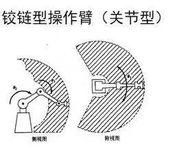
 2. Articulated Manipulator (Joint Type)The joints of articulated robots are all rotational, similar to a human arm, and are the most common structure in industrial robots. Its working range is relatively complex.① Rapid inspection and product development of automotive parts, molds, sheet metal parts, plastic products, sports equipment, glass products, ceramics, aerospace, etc.② Three-dimensional coordinate measurement and error detection for body assembly and general machinery assembly quality control.③ Rapid prototyping of antiques, artworks, sculptures, cartoon figures, portrait products, etc.④ On-site measurement and inspection of complete vehicles.⑤ Body shape measurement, medical device manufacturing, human shape production, and medical cosmetic procedures.
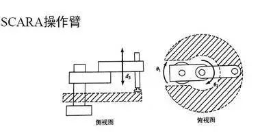
 3. SCARA ManipulatorSCARA robots are commonly used for assembly tasks, characterized by their high flexibility in the x-y plane and strong rigidity along the z-axis, providing selective flexibility. This type of robot has achieved good applications in assembly tasks.① Widely used for assembling printed circuit boards and electronic components.② Moving and placing objects, such as integrated circuit boards.③ Widely applied in the plastic industry, automotive industry, electronics industry, pharmaceutical industry, and food industry.④ Handling parts and assembly work.
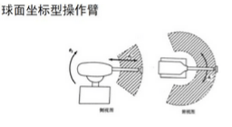
 4. Spherical Coordinate ManipulatorFeatures: Large working range near the central support, two rotating drive devices are easy to seal, covering a large workspace. However, the coordinates are complex and difficult to control, and the linear drive devices have sealing issues.
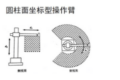
 5. Cylindrical Coordinate ManipulatorAdvantages: Simple calculations; linear sections can use hydraulic drive, providing considerable power; can reach inside cavity-type machines. Disadvantages: The space reachable by its arms is limited and cannot access areas near columns or close to the ground.The linear drive part is difficult to seal and dustproof; when the rear arm operates, the back end of the arm may collide with other objects within the working range.
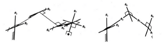
 6. Redundant MechanismsTypically, spatial positioning requires six degrees of freedom, and additional joints can help the mechanism avoid singular configurations. The following diagram shows a 7-degree of freedom manipulator configuration.
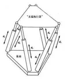
 7. Closed-loop StructureA closed-loop structure can improve the rigidity of the mechanism but will reduce the joint motion range, thus decreasing the working space.① Motion simulators;② Parallel machine tools;③ Micromanipulation robots;④ Force sensors;⑤ Cell manipulation robots in biomedical engineering, capable of injecting and dividing cells;⑥ Microscopic surgical robots;⑦ Attitude adjustment devices for large radio telescopes;⑧ Hybrid equipment, such as SMT’s Tricept hybrid robotic arm module, which is a successful example of modular design based on parallel mechanism units.
 Common structural forms of industrial robots (diagram)
 2. Main Technical Parameters of RobotsThe technical parameters of robots reflect the work they can perform and their highest operational performance, which are essential considerations in the design and application of robots. The main technical parameters of robots include degrees of freedom, resolution, working space, working speed, and working load.1. Degrees of FreedomThe number of independent coordinate axes that a robot can move. The degrees of freedom of a robot refer to the number of independent motion parameters required to determine the position and orientation of the robot’s end effector in space. The opening and closing of fingers, as well as the degrees of freedom of finger joints, are generally not included. The degrees of freedom of a robot are usually equal to the number of joints. The commonly used degrees of freedom for robots generally do not exceed 5-6.2. JointsAlso known as motion pairs, these allow relative motion between the various components of the robot arm.
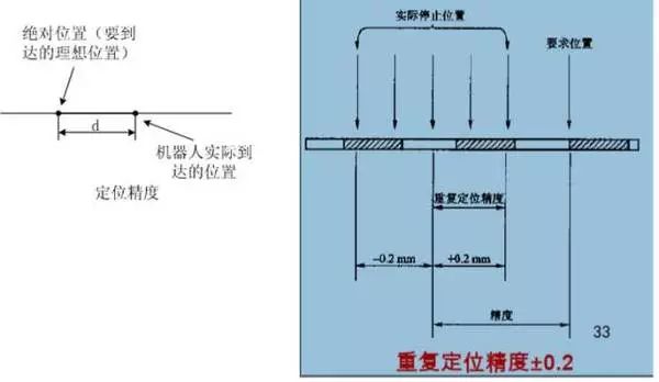
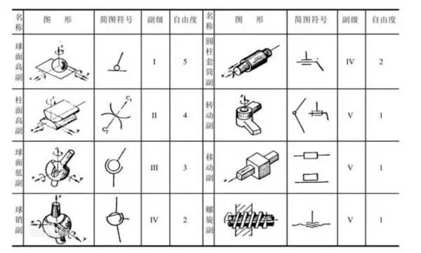 3. Working SpaceThe total spatial area that the robot’s arm or end effector can reach. Its shape depends on the number of degrees of freedom and the types and configurations of the joints. The working space of a robot is typically represented using graphical and analytical methods.4. Working SpeedThe distance or angle that the mechanical interface center or tool center point moves in unit time during uniform movement under working load conditions.5. Working LoadThe maximum load that a robot can bear at any position within its working range, generally expressed in terms of mass, torque, and moment of inertia. It is also related to the direction and magnitude of running speed and acceleration, with the weight of the workpiece that can be grasped at high speed being specified as the load capacity indicator.6. ResolutionThe smallest distance of movement or the smallest angle of rotation that can be achieved.7. AccuracyRepeatability or repeat positioning accuracy: refers to the degree of difference when a robot repeatedly reaches a target position. Or the dispersion of the robot’s position when continuously repeating the same position command. It measures the intensity of error values, i.e., repeatability.
 3. Common Materials Used in Robots1) Carbon structural steel and alloy structural steel. These materials have good strength, especially alloy structural steel, which has increased strength by 4-5 times, a large elastic modulus E, and strong resistance to deformation, making them the most widely used materials.2) Aluminum, aluminum alloys, and other lightweight alloy materials. These materials share the common characteristic of being lightweight, with a relatively small elastic modulus E, but their low density allows the E/ρ ratio to be comparable to that of steel. Some rare aluminum alloys have seen significant improvements in quality, such as aluminum alloys with 3.2% (weight percent) lithium, which have seen a 14% increase in elastic modulus and a 16% increase in E/ρ ratio.3) Fiber-reinforced alloys. These alloys, such as boron fiber-reinforced aluminum alloys and graphite fiber-reinforced magnesium alloys, achieve E/ρ ratios of 11.4×10⁷ and 8.9×10⁷, respectively. These fiber-reinforced metallic materials have a very high E/ρ ratio but are expensive.4) Ceramics. Ceramic materials have good quality but are brittle and difficult to process. Japan has already developed samples of ceramic robot arms used in small high-precision robots.5) Fiber-reinforced composite materials. These materials have an excellent E/ρ ratio and outstanding damping properties. Traditional metallic materials cannot achieve such high damping, so instances of composite materials being used in high-speed robots are increasing.6) Viscoelastic damping materials. Increasing the damping of robot link components is an effective method to improve the dynamic characteristics of robots. Currently, many methods are used to increase the damping of structural materials, with one of the most suitable methods for robots being the use of viscoelastic damping materials for constrained layer damping treatment of original components.4. Main Structures of Robots
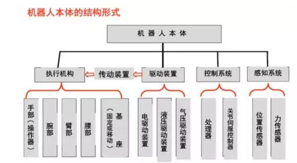 (1) Robot Drive DevicesConcept: To make a robot operate, drive devices must be installed for each joint, i.e., each degree of freedom. Function: To provide the primary power for the movements of various parts and joints of the robot.The drive system can be hydraulic, pneumatic, electric, or a combination of these systems; it can be direct drive or indirectly driven through mechanical transmission mechanisms such as synchronous belts, chains, gear trains, and harmonic gears.1. Electric Drive Devices
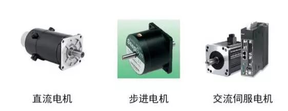 Electric drive devices have simple energy sources, a wide range of speed variations, high efficiency, and high speed and position accuracy. However, they are often linked with reduction devices, making direct drive difficult.Electric drive devices can be divided into DC (DC), AC servo motor drives, and stepper motor drives. DC servo motors have brushes that wear easily and can produce sparks. Brushless DC motors are becoming increasingly popular. Stepper motor drives are usually open-loop controls, simple to control but with limited power, mostly used in low-precision, low-power robot systems.Before powering on electric drives, the following checks should be made:1) Is the power supply voltage suitable (over-voltage may damage the drive module)? For DC inputs, the +/- polarity must not be reversed; is the motor model or current setting on the drive controller appropriate (do not start with too high a value)?2) Ensure control signal lines are securely connected; in industrial settings, consider shielding issues (e.g., using twisted pairs);3) Do not connect all necessary wires at the start; only connect the most basic system first, and gradually connect more after confirming it runs well.4) Be clear about the grounding method, or use floating connections.5) Closely monitor the motor’s status during the first half-hour of operation, such as whether it moves normally, its noise, and temperature rise; if any issues are found, stop and adjust immediately.2. Hydraulic DriveHydraulic drive is completed through high-precision cylinders and pistons, achieving linear motion through the relative movement of the cylinder and piston rod.Advantages: High power, can eliminate the need for reduction devices by connecting directly to the driven rods, compact structure, good rigidity, fast response, and high precision in servo drives.Disadvantages: Requires an additional hydraulic source and is prone to liquid leakage.Not suitable for high or low-temperature environments, so hydraulic drives are mostly used in very high power robot systems.Select suitable hydraulic oil. Prevent solid contaminants from entering the hydraulic system, and prevent air and water from invading the hydraulic system. Mechanical operations should be gentle and smooth; rough operations will inevitably cause impact loads, frequent mechanical failures, and significantly shorten service life. Be aware of cavitation and overflow noise. Always pay attention to the sounds of hydraulic pumps and overflow valves during operation; if the hydraulic pump produces “cavitation” noise that cannot be eliminated after venting, investigate the cause and resolve any faults before use. Maintain suitable oil temperatures; the working temperature of hydraulic systems should generally be controlled between 30-80°C.3. Pneumatic DrivePneumatic drive has a simple structure, is clean, and has sensitive actions with cushioning effects. However, compared to hydraulic drives, it has lower power, poor rigidity, high noise, and difficult speed control, so it is mostly used in robots with lower precision for point control.(1) Features fast speed, simple system structure, easy maintenance, and low cost, making it suitable for medium and small load robots. However, due to difficulties in achieving servo control, it is often used in program-controlled robots, such as in loading and unloading and stamping robots.(2) In most cases, it is used for two-position or limited point control in medium and small robots.(3) Control devices often use programmable logic controllers (PLC controllers). In flammable and explosive environments, pneumatic logic components can be used to form control devices.(2) Linear Transmission Mechanism.The transmission device is a key part connecting the power source and the motion links. Depending on the form of joints, common transmission mechanisms include linear transmission and rotational transmission mechanisms.Linear transmission methods can be used for the X, Y, Z drives of Cartesian robots, radial drive and vertical lift drive of cylindrical coordinate structures, and radial telescopic drive of spherical coordinate structures.Linear motion can convert rotational motion into linear motion through transmission elements like gear racks, lead screws, or can be driven directly by linear drive motors or by the pistons of cylinders or hydraulic cylinders.1. Gear Rack DeviceTypically, the rack is fixed. The rotational motion of the gear is converted into linear motion of the platform.Advantages: Simple structure.Disadvantages: Large backlash.
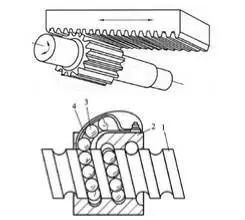 2. Ball ScrewIn ball screws, balls are embedded in the helical grooves of the screw and nut, allowing the balls to circulate continuously through the guiding grooves in the nut.Advantages: Low friction, high transmission efficiency, no crawling, and high precision.Disadvantages: High manufacturing costs and complex structure.Self-locking issues: Theoretically, ball screw pairs can be self-locking, but in practical applications, this self-locking is rarely used.The main reasons are: poor reliability or high processing costs; because the diameter to lead ratio is very large, a set of worm gear or similar self-locking devices is usually added.(3) Rotational Transmission MechanismThe purpose of using rotational transmission mechanisms is to convert the higher rotational speed output by the motor’s drive source into a lower speed while obtaining greater torque. Common rotational transmission mechanisms used in robots include gear chains, synchronous belts, and harmonic gears.1. Gear Chain(1) Speed relationship;(2) Torque relationship.2. Synchronous BeltA synchronous belt has many teeth and meshes with a similarly toothed synchronous pulley. During operation, it functions like a soft gear.Advantages: No slipping, good flexibility, low cost, and high repeat positioning accuracy.Disadvantages: Has some elastic deformation.3. Harmonic GearA harmonic gear consists of three main components: a rigid gear, a harmonic generator, and a flexible gear. Typically, the rigid gear is fixed while the harmonic generator drives the flexible gear to rotate. Main features:(1) Large transmission ratio, single-stage 50~300.(2) Smooth transmission with high load capacity.(3) High transmission efficiency, reaching 70%~90%.(4) High transmission accuracy, 3~4 times higher than ordinary gear transmission.(5) Backlash is small, less than 3’.(6) Cannot achieve intermediate output; the flexibility of the flexible gear is relatively low.Harmonic transmission devices have been widely used in countries with advanced robotics technology. In Japan, for example, 60% of robot drive devices use harmonic transmission.The robot sent to the moon by the United States used harmonic transmission devices for all its joints, with one arm using 30 harmonic transmission mechanisms.The mobile robot “Lunokhod” sent to the moon by the former Soviet Union had eight wheels driven separately by closed harmonic transmission mechanisms. Robots developed by Volkswagen in Germany, such as the ROHREN and GEROT R30 models, and the VERTICAL 80 model developed by Renault in France, all use harmonic transmission mechanisms.(4) Robot Sensor Systems1. The sensory system consists of internal and external sensor modules to obtain meaningful information about the internal and external environmental states.2. The use of intelligent sensors improves the mobility, adaptability, and intelligence levels of robots.3. The use of intelligent sensors improves the mobility, adaptability, and intelligence levels of robots.4. For some specific information, sensors are more effective than human sensory systems.(5) Robot Position DetectionRotary optical encoders are the most commonly used position feedback devices. Photoelectric detectors convert light pulses into binary waveforms. The angle of the axis is determined by calculating the number of pulses, while the direction of rotation is determined by the relative phase of two square wave signals.Inductive synchronizers output two analog signals—the sine and cosine signals of the axis angle. The angle of the axis is calculated from the relative amplitudes of these two signals. Inductive synchronizers are generally more reliable than encoders but have lower resolution.Potentiometers provide the most direct form of position detection. They are connected in a bridge circuit and can generate a voltage signal proportional to the axis angle. However, they suffer from low resolution, poor linearity, and are sensitive to noise.Speedometers can output an analog signal proportional to the speed of the axis. If such speed sensors are not available, speed feedback signals can be obtained by differentiating the detected position concerning time.(6) Robot Force DetectionForce sensors are typically installed in three positions on the manipulator arm:1. Mounted on the joint drive. It can measure the torque or force output of the driver/reducer itself but cannot effectively detect the contact force between the end effector and the environment.2. Installed between the end effector and the terminal joint of the manipulator arm, called a wrist force sensor. Generally, it can measure three to six force/torque components applied to the end effector.3. Mounted on the “fingertip” of the end effector. Typically, these force-sensitive fingers have built-in strain gauges that can measure one to four components of force applied to the fingertip.(7) Robot-Environment Interaction System1. The robot-environment interaction system is a system that enables industrial robots to connect and coordinate with external devices in their environment.2. Industrial robots integrate with external devices to form functional units, such as processing and manufacturing units, welding units, assembly units, etc. They can also integrate multiple robots, multiple machine tools or devices, and multiple parts storage devices into a unit to perform complex tasks.(8) Human-Robot Interaction SystemThe human-robot interaction system is a device that allows operators to participate in robot control and communicate with the robot. This system can be summarized into two main categories: command input devices and information display devices.5. Robot Control Systems1. Robot Control SystemsThe purpose of “control” is to make the controlled object exhibit the desired behavior by the controller. The basic condition for “control” is to understand the characteristics of the controlled object. The essence is to control the output torque of the driver.
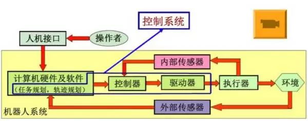 2. Robot Teaching Principles
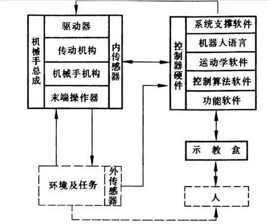 The basic working principle of robots is teaching and reproduction. Teaching, also known as guiding, involves the user guiding the robot step by step through the actual task, with the robot automatically memorizing the position, posture, motion parameters/process parameters of each action during the guiding process, and automatically generating a continuous program to execute all operations. After teaching, only a start command is needed for the robot to execute all operations accurately according to the taught actions.3. Classification of Robot Control:1) Divided into open-loop control and closed-loop control based on feedback; open-loop precise control conditions: precisely knowing the model of the controlled object, and this model remains unchanged during control.2) Divided into position control, force control, and hybrid control based on desired control quantities; position control can be further divided into single-joint position control (position feedback, position speed feedback, position speed acceleration feedback), multi-joint position control, and multi-joint position control can be subdivided into decomposed motion control and centralized control; force control can be divided into direct force control, impedance control, and force-position hybrid control.3) Intelligent control methods: fuzzy control, adaptive control, optimal control, neural network control, fuzzy neural network control, expert control, and others.4. Hardware Configuration and Structure of Control Systems:Due to the large number of coordinate transformations and interpolation calculations involved in robot control, as well as lower-level real-time control, most current robot control systems adopt a layered structure of microcomputer control systems, typically using a two-level computer servo control system.
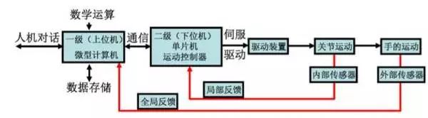 1) Specific Process:After the main control computer receives the operational command input by the staff, it first analyzes and interprets the command, determining the motion parameters of the hand.Then perform kinematic, dynamic, and interpolation calculations, ultimately deriving the coordinated motion parameters for each joint of the robot. These parameters are output to the servo control level through communication lines as the set signals for each joint servo control system. The joint drivers convert this signal from D/A to drive each joint to produce coordinated motion. Sensors feed back the motion output signals of each joint back to the servo control level computer, forming a local closed-loop control for more precise control of the robot’s end effector motion in space.2) PLC-based Motion ControlTwo control methods:1. Using certain output ports of the PLC to generate pulse output commands to drive the motor while using general I/O or counting components to achieve closed-loop position control of the motor.2. Using an externally extended position control module of the PLC to achieve closed-loop position control of the motor, mainly using high-speed pulse control, which belongs to the position control method, with point-to-point position control being more common.

Source | Industrial Robots
Previous Reviews
●Nine-Year Consistent Public Boarding School Longtan “Jiaxiang” Set to Begin Construction
● Entrepreneurs Gather to Strengthen Chains and Enhance New Heights
●“Listed Backup Army” | Chenghua Adds 6 New “Seed Players”
●Promoting Innovation-Driven Development, Chengdu Accelerates
●Technological Upgrades Empower! Four Projects from Functional Areas Listed as Provincial Key Project


Like Your Most Beautiful!