In-Vehicle Cameras: The Eyes of Autonomous Driving
In-vehicle cameras are known as the “eyes of autonomous driving” and are the core sensing devices in ADAS systems and the field of automotive autonomous driving. They mainly collect image information through lenses and image sensors, achieving 360° visual perception and compensating for radar’s shortcomings in object recognition, making them the sensors closest to human vision.
In-vehicle cameras are widely used in the automotive field, gradually expanding from early applications in driving recorders, reversing images, and parking surround views to behavior recognition in smart cockpits and ADAS-assisted driving, with an increasingly rich array of application scenarios.
Currently, the global market concentration of the in-vehicle camera industry is high, with the CR3 at 41%, and the top ten companies occupying 96% of the market share.
The Highway Loss Data Institute (HLDI) in the United States predicts that by 2030, nearly 50% of vehicles will be equipped with ADAS technology.
According to ICVTank, the scale of China’s in-vehicle camera industry is expected to reach 23 billion by 2025, with a 5-year CAGR of 30%; the global in-vehicle camera market is projected to grow from $11.2 billion in 2019 to $27 billion by 2025, with a 5-year CAGR of 15.8%.
Autonomous driving includes perception, judgment, and execution, with perception being the source of the entire process and an important module of the autonomous driving system. During the driving process, the perception system collects information about the surrounding environment in real-time through sensors, akin to the “eyes” of autonomous vehicles, helping them achieve observational capabilities similar to those of human drivers.
In autonomous vehicles, the perception system mainly consists of cameras, millimeter-wave radar, and optional laser radar (here mainly to avoid conflict with Tesla fans). Cameras play a crucial role as the primary environmental perception sensors, enabling 360° comprehensive visual perception, compensating for radar’s shortcomings in object recognition, and making them one of the key devices in the field of autonomous driving.
What is an In-Vehicle Camera?
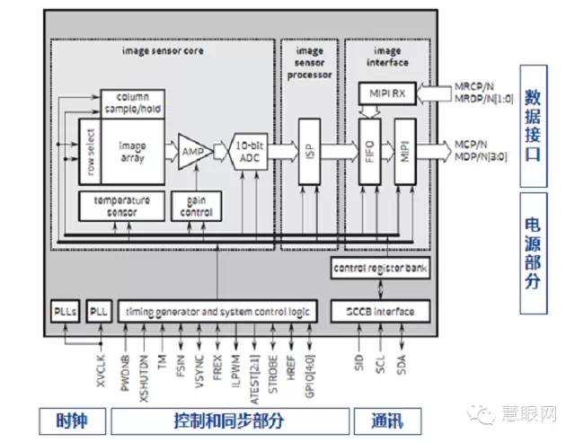
The main hardware structure of in-vehicle cameras includes optical lenses (which comprise optical glass, filters, protective films, etc.), image sensors, Image Signal Processors (ISP), serializers, connectors, and other components. The schematic structure is shown in the figure below:
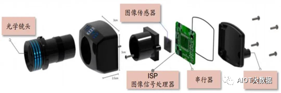
The structure of the in-vehicle camera (Image source: ON Semiconductor)
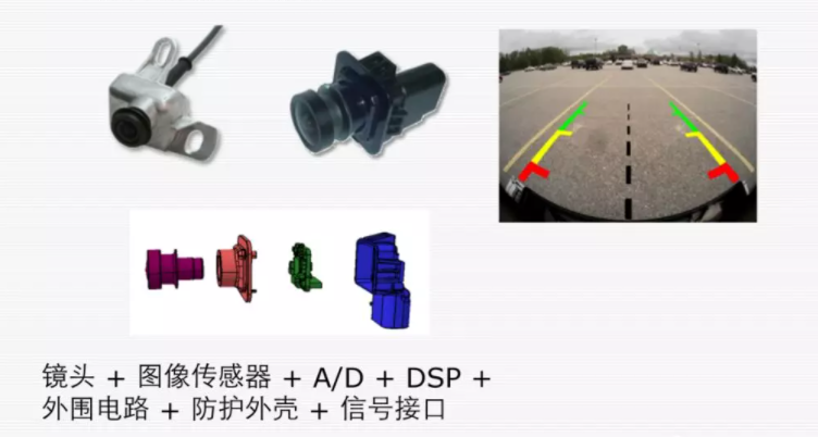
The structure of the in-vehicle camera is shown in the above figure. If placed outside the vehicle, it needs to form a complete camera; if it is a DVR inside the vehicle, waterproofing is not a concern, and it can be assembled into the above camera module.
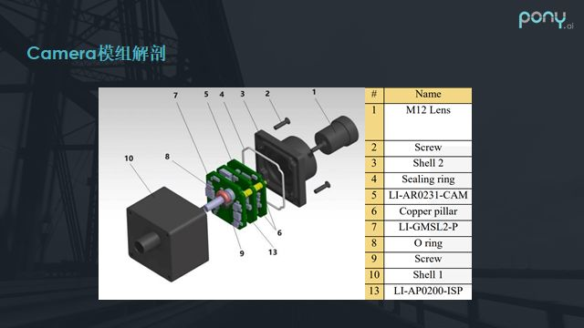
The above image shows a common camera module used in vehicles. Besides the outer aluminum shell, sealing ring, and lens, the middle consists of several simple layers of boards, typically including a sensor board, a small board for the image processor, and a serializer board. The serializer is necessary because the image data output bus of the camera sensor or ISP usually follows the MIPI CSI standard, which is characterized by high speed but short transmission distances; otherwise, signal integrity cannot be guaranteed.
Therefore, in vehicles, we need to convert it to high-speed bus standards suitable for long-distance transmission, such as GMSL. Thus, the camera module typically converts the bus through the serializer board. Additionally, coaxial cables can provide power to the module and transmit image data.
Optical Lens: Responsible for focusing light and projecting objects in the field of view onto the imaging medium’s surface, depending on the imaging effect requirements, multiple layers of optical glass may be needed. Filters can eliminate light wavelengths invisible to the human eye, leaving only the visible light spectrum of the actual scene within the human visual range.
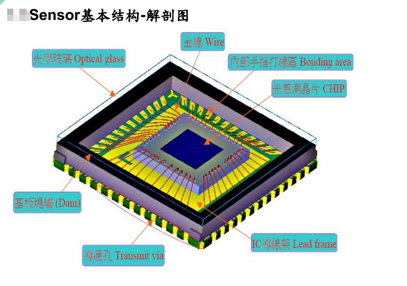
Image Sensor: The image sensor can use the photoelectric conversion function of photoelectric devices to convert the light image on the photosensitive surface into an electrical signal proportional to the light image. They are mainly divided into CCD and CMOS types.
ISP Image Signal Processor: Mainly uses hardware structure to preprocess the RAW format data from the image video source input by the image sensor, converting it to formats like YCbCr. It can also perform various tasks such as image scaling, automatic exposure, automatic white balance, and automatic focusing.
Serializer: Transmits the processed image data and can be used to transmit various types of image data such as RGB and YUV.
Connector: Used to connect and secure the camera.
In-vehicle cameras also require higher manufacturing processes and reliability than industrial and commercial cameras. Since vehicles need to operate in harsh environments for extended periods, in-vehicle cameras must work stably under complex conditions such as high and low temperatures, strong vibrations, and high humidity. The manufacturing requirements are mainly as follows:
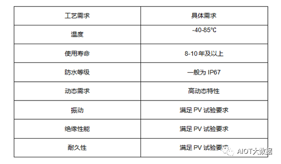
Requirements for in-vehicle camera manufacturing
-
High-Temperature Resistance: In-vehicle cameras must operate normally within a range of -40°C to 85°C and adapt to extreme temperature changes; -
Shock Resistance: Vehicles driving on uneven roads produce strong vibrations, so in-vehicle cameras must withstand various intensities of vibration; -
Magnetic Resistance: High electromagnetic pulses are generated when vehicles start, requiring high magnetic resistance; -
Water Resistance: In-vehicle cameras must be tightly sealed and able to operate normally after being submerged in rainwater for several days; -
Service Life: The service life must be at least 8-10 years to meet requirements; -
Ultra-Wide Angle: Side view surround cameras must be ultra-wide angle, with a horizontal field of view reaching 135°; -
High Dynamic Range: Vehicles travel at high speeds, and the lighting environment changes rapidly and frequently, requiring the camera’s CMOS to have high dynamic characteristics; -
Low Noise: The camera should effectively suppress noise in low light conditions, especially requiring side view and rear view cameras to capture clear images even at night.
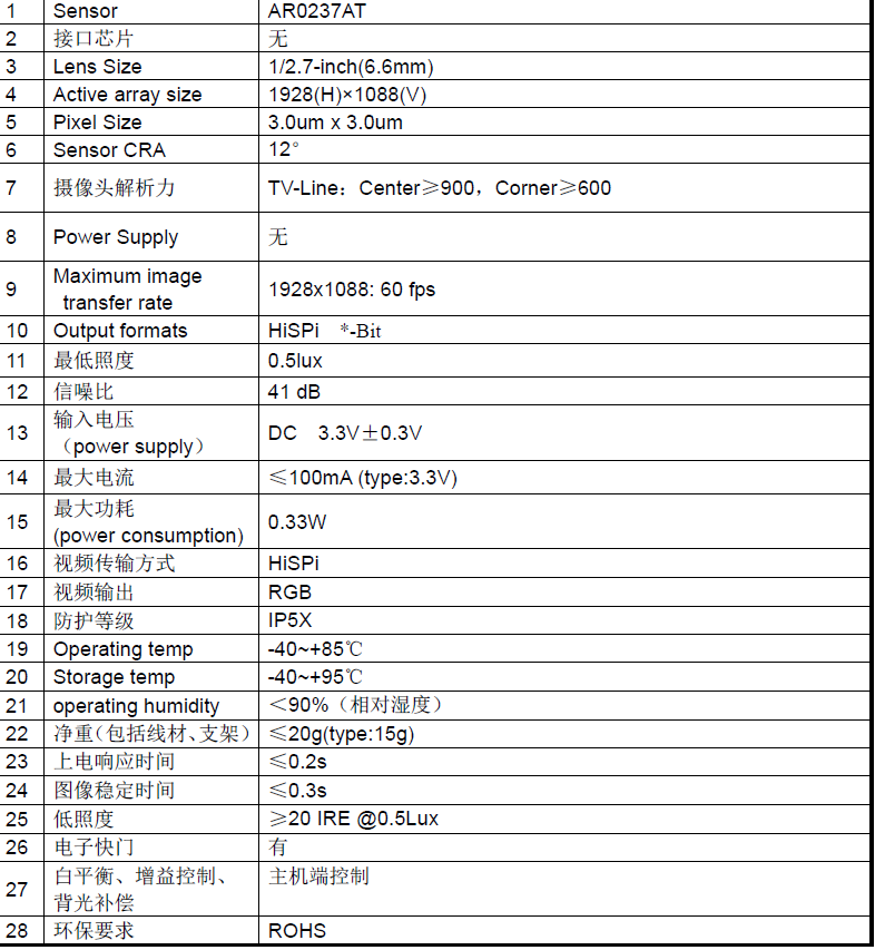
Key Parameters of In-Vehicle Smart Front Cameras
-
Detection Distance -
Horizontal Field of View -
Vertical Field of View -
Resolution – The maximum number of lines visible on a monitor (higher resolution than the camera) when the camera captures black and white alternating stripes at equal intervals. When exceeding this number, the screen appears gray and cannot distinguish black and white stripes. -
Minimum Illumination – The minimum light required for the image sensor to function, or the lowest lighting level for normal imaging. This is the illumination value when the video signal level of the camera drops below half the maximum value as the object’s illumination decreases. -
Signal-to-Noise Ratio – The ratio of the output signal voltage to the simultaneously output noise voltage; -
Dynamic Range – The range of brightness values of the brightest and darkest objects that can be normally displayed in the same image captured by the camera. The larger the dynamic range, the better the ability to display overexposed or underexposed objects in the same frame.
Advantages Compared to Radar Technology
-
Object Recognition and Classification – Currently, ordinary 3D millimeter-wave radar can only detect whether there are obstacles ahead but cannot accurately identify the size and type of obstacles; for instance: lane line recognition, traffic light recognition, and traffic sign recognition; -
Free Space Detection – Defining the safe boundary for vehicle travel (drivable area), mainly delineating vehicles, ordinary curbs, visible boundaries without obstacles, and unknown boundaries; -
Detection Ability for Laterally Moving Targets, such as pedestrians and vehicles crossing at intersections; -
Localization and Map Creation – This refers to visual SLAM technology. Although there is also SLAM using millimeter-wave radar, visual SLAM technology is more mature and has better application prospects;
-
Traffic Light Recognition and Traffic Sign Recognition -
Cost advantage, and the algorithms and technology are more mature -
High Object Recognition Rate
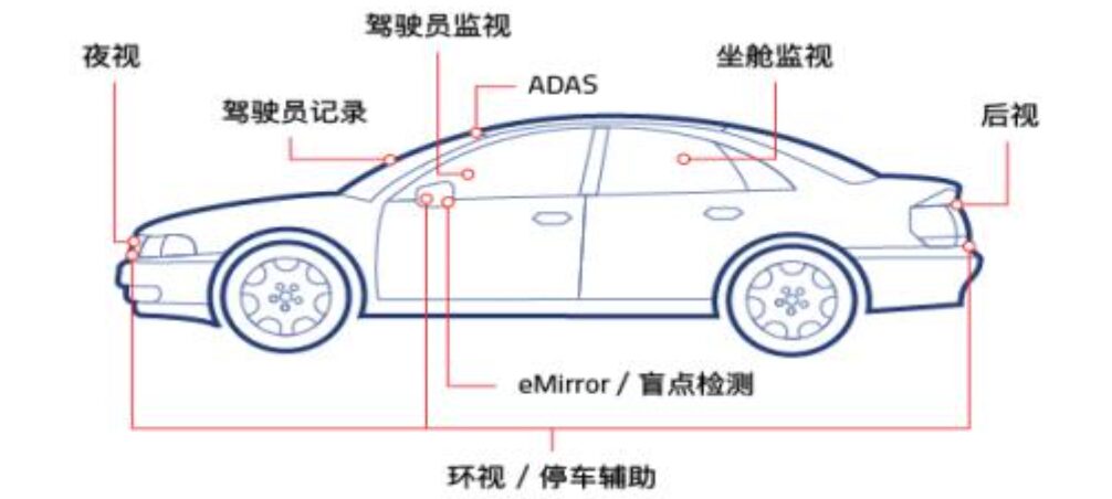
Distribution of In-Vehicle Cameras:
 Data Source: CIOE China Optics Fair
Currently, in-vehicle cameras are mainly categorized based on installation positions into front cameras, surround cameras, rear cameras, side cameras, and built-in cameras.
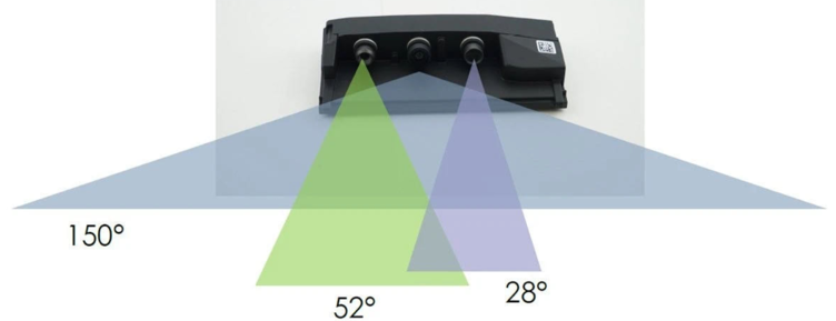
Front Cameras: Generally installed on the windshield, used for visual perception and recognition functions during driving. Depending on functionality, they can be further divided into main front cameras, narrow-angle front cameras, and wide-angle front cameras.
Main Front Cameras: Used as the main camera in L2 ADAS systems. Their field of view typically ranges from 30°, 50°, 60°, 100°, to 120°, with a detection distance generally between 150 – 170 m, and the camera output format is RCCB or RCCC.
Wide-Angle Front Cameras: Mainly used to recognize nearby objects, primarily for urban road conditions, low-speed driving, etc., with a field of view between 120° – 150° and a detection distance of about 50 m. After the large-scale installation of 8MP lenses, this camera may no longer be needed.
Narrow-Angle Front Cameras: Mainly used for recognizing traffic lights, pedestrians, and other targets, typically using narrow-angle lenses with angles around 30 – 40°. The pixel density is generally consistent with that of the main front camera, and this camera has a narrow angle, offering higher pixel density and longer detection distances, generally reaching up to 250 m or even further.
After the installation of the 8MP camera, the FOV of the main front camera can reach 120°, and this camera may no longer be necessary. The detection distance is around 60 m.
Surround Cameras: Generally installed around the vehicle, typically using 4 – 8 cameras, which can be divided into front fisheye cameras, left-side fisheye cameras, right-side fisheye cameras, and rear fisheye cameras. They are used for panoramic surround view display and visual perception and target detection for parking functions; the common color matrix is RGGB due to the need for color restoration.
Rear Cameras: Generally installed on the trunk, mainly for parking assistance. The field of view ranges from 120 – 140°, with a detection distance of about 50 m.
Side Front Cameras: Installed on the B-pillar or the vehicle’s rearview mirror, the field of view is generally between 90° – 100°, with a detection distance of about 80 m. This camera is mainly used for detecting side vehicles and bicycles.
Side Rear Cameras: Generally installed on the vehicle’s front fender, the field of view is generally around 90°, with a detection distance also around 80 m, mainly used for lane changes and merging into other roads.
Built-in Cameras: Mainly used to monitor driver status and implement fatigue reminders.
Among these, the front camera is relatively expensive, with current market prices ranging from 300 – 500 Yuan; the other cameras are priced around 150 – 200 Yuan.
Mainstream Manufacturers’ In-Vehicle Camera Solutions
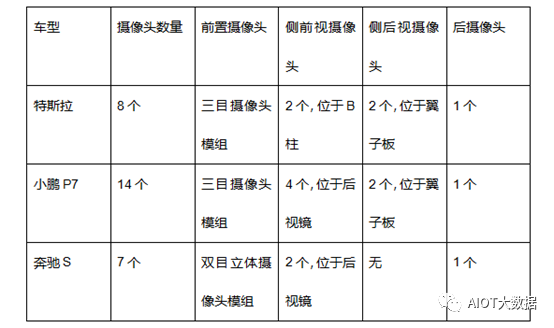
From the solutions, we can see that Tesla’s 8 cameras are all related to the driving system, which is closely related to its advertised pure visual autonomous driving solution that does not rely on lidar. The biggest advantage of Tesla’s solution is its high cost performance. Tesla has achieved L2+ level autonomous driving using a self-developed 1.2MP camera at a very low cost.
Xpeng P7 uses multiple cameras, and the biggest advantage of this solution is its strong scalability. The initial design requires a higher hardware cost, but after OTA upgrades, its autonomous driving functions have excellent compatibility and scalability.
Through this sensor model, Xpeng has achieved a well-experienced L2+ level autonomous driving function, including its unique high-speed autonomous navigation driving (NGP) and parking memory functions.
The Mercedes-Benz S-Class represents the traditional OEM solution, with the dual-camera stereo camera scheme being the biggest advantage of the S-Class. Compared to single-lens cameras, dual-lens cameras can calculate the motion of current detected targets in the X, Y, Z coordinates, determine the posture and type of detected targets, and the experience of Mercedes-Benz’s L2 level ADAS functions is also better than the other two companies.
In the analysis of camera solutions for already mass-produced models, we find that they all use medium to low pixel cameras to achieve autonomous driving functions.
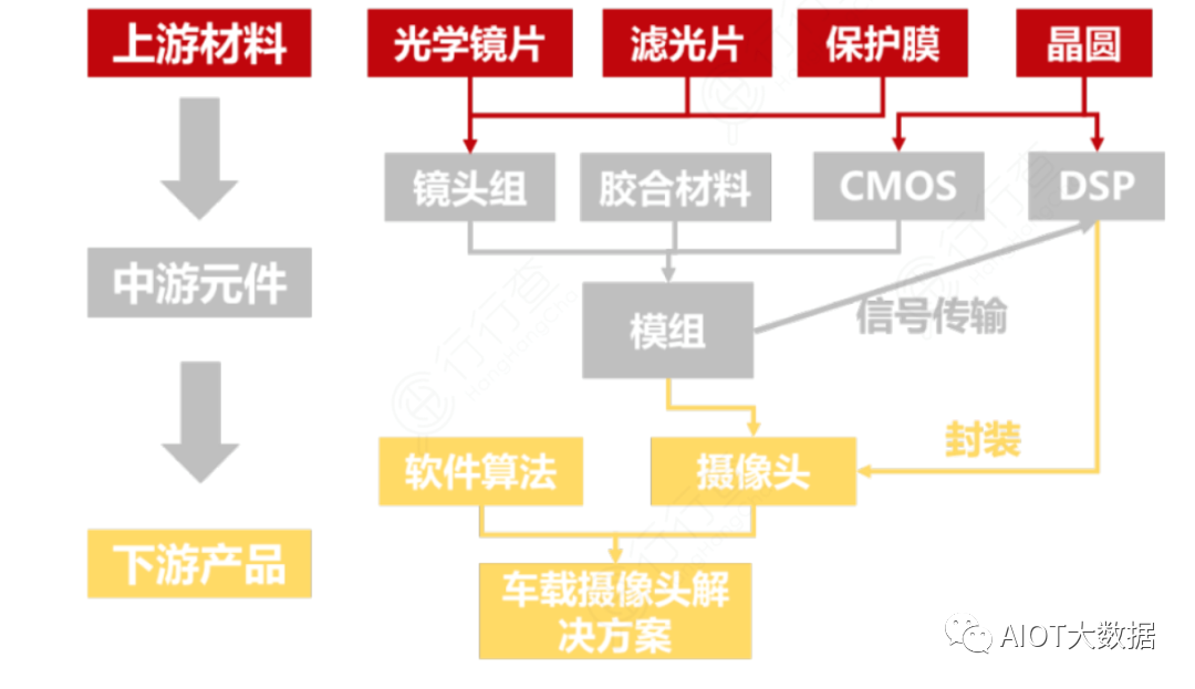
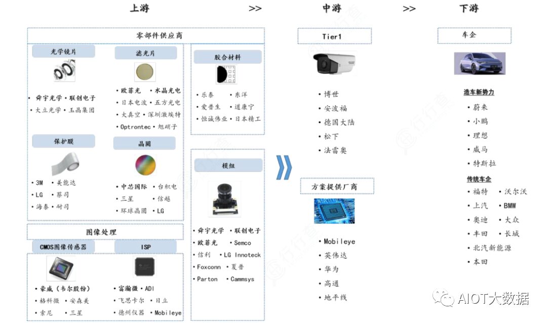
In-Vehicle Camera Industry Chain
The in-vehicle camera industry chain mainly involves three key links: upstream materials, midstream components, and downstream products.
Upstream materials include optical lenses, filters, and protective films used to manufacture lens groups, while wafers are used to manufacture CMOS chips and DSP signal processors. In the midstream, lens groups, CMOS chips, and adhesive materials are assembled into modules and packaged with DSP signal processors to form camera products.
At this level of the industry chain, upstream suppliers can already provide complete camera products to downstream vehicle manufacturers or first-tier suppliers. In the in-vehicle camera industry chain, cameras and software algorithms together form in-vehicle camera solutions used in autonomous vehicles.
Currently, companies with significant market shares in the in-vehicle camera market are mainly leading global first-tier component suppliers, with downstream customers covering major vehicle manufacturers worldwide.
CMOS accounts for the highest cost share in in-vehicle cameras, reaching 52%; module packaging accounts for 20%, and optical lenses account for 19%.
CMOS Chips
CMOS (CIS sensor) is the mainstream photosensitive element solution for in-vehicle cameras. Compared to CCD photosensitive elements, CMOS has slightly inferior imaging quality but is lower in cost and more energy-efficient, making it widely favored in the field of in-vehicle cameras where pixel requirements are not high.
The CMOS manufacturing industry chain is mainly divided into three links: design, foundry, and packaging/testing, and is ultimately assembled and integrated into camera modules for sale to downstream application manufacturers.
Due to the design process of the pixel layer in CMOS chips being similar to that of analog chips, the manufacturing process requirements are high. Therefore, leading companies like Sony and Samsung adopt the IDM model, while Chinese companies like OmniVision and GalaxyCore mostly use the Fabless model.
In terms of foundry, TSMC, Huahong, SMIC, Powerchip, and SK Hynix are the main global suppliers of CIS wafers.
In terms of packaging, the global CIS packaging capacity is concentrated in Taiwan, with major CIS packaging manufacturers including Chipbond, STMicroelectronics, and Tongxin Electronics. Domestic companies like Crystal Technology and Huatian Technology also have CIS packaging capabilities.
According to Yole data, in 2019, the automotive market in the downstream CIS market grew by 41%, far exceeding other major fields like mobile phones, computers, security, and industrial control.
CMOS manufacturing technology is highly sophisticated and is currently primarily occupied by foreign enterprises in the global market.
From a competitive landscape perspective, ON Semiconductor holds the largest market share at 36%, followed by OmniVision at 22%, with Sony, Panasonic, and Samsung closely behind. The top 3 global CIS suppliers account for over 65% of the market, indicating high industry concentration. Domestic company Will Semiconductor has entered the CIS field through the acquisition of OmniVision, becoming a leading enterprise in the CIS sector.
Preliminary Introduction to Camera Image Processing ISP
Let’s take a look at the key parameters of the in-vehicle camera module, which may not have been fully explained, such as white balance, automatic gain control, color restoration, etc. The above camera description pertains to host control, and here we need to explain a key component, the Image Signal Processor (ISP), which is responsible for many tasks.
The diagram below shows the basic composition of the vehicle system: yellow arrows represent data transmission, while blue arrows represent control signal transmission.
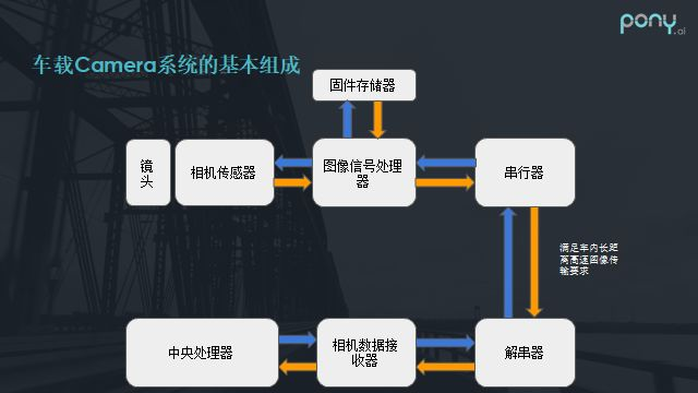
The image processing flow of the camera is roughly as follows:
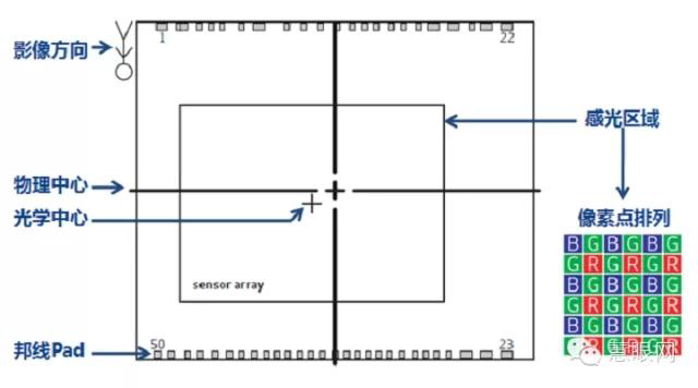
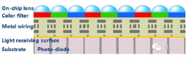
After the camera senses charges, they are converted into digital signals for each pixel, which we can refer to as a Bayer pattern. Once the Bayer pattern enters the ISP, it undergoes a series of image processing before becoming a normal preview or captured image.
Key steps in image processing include performing white balance, as human vision corrects the colors seen. For instance, when illuminated by yellow light, white paper appears yellow instead of white. Therefore, correcting white balance is crucial, and after white balance adjustment, demosaicing is performed to restore all color channels for each pixel.
Next, any color deviations caused by the characteristics of each sensor or other reasons need to be corrected through matrix multiplication for color calibration. Then, the process needs to transition to the YCbCr domain for noise reduction or compensation for brightness or color channels. Overall, this is a very simplified process; in actual vehicle applications, the process is much more complex, involving more algorithms such as HDR multi-frame exposure, synthesis, tone mapping, etc.
The placement of the ISP is critical:
Some may place the ISP chip in the camera, transmitting the processed signal to the host, while others may not include an ISP chip, allowing the host’s built-in ISP chip to handle image processing. This arrangement improves heat dissipation and reduces radiation at the camera end.
For example, in the case of a rearview camera, the distance from the camera to the host is typically 5-8 meters, depending on the vehicle’s length. This component usually has the ISP placed at the camera module end, meaning the signals transmitted are those processed by the ISP, enhancing anti-interference capabilities. The downside is that it increases the size and requires high heat dissipation.
Conversely, in some DVR cameras, where the distance from the camera to the control host CPU is very short and design requirements are high, the ISP is placed on the CPU side (many DVR CPUs have built-in ISP chips), making it the optimal solution in terms of cost and design.
As previously mentioned, the signals from the camera must undergo ISP processing. So how does the ISP process these signals, and what are the procedures involved? This relates to color-related content; first, we will provide an overview of color-related topics and then explain how the ISP processes these signals.
Adjusting the effects of the camera sensor involves numerous parameters. If one can deeply understand the basic optical principles and the principles of image processing related to sensor software/hardware, it will greatly enhance our work efficiency. Otherwise, lacking theoretical guidance can lead to reliance on intuition and experience, often failing to grasp the key issues and the core technologies for sensor debugging, thereby not fundamentally solving problems.
Optical Components
The optical devices within the lens group (mainly including lenses, filters, and protective films) play a crucial role in the image quality generated by the camera.
For example, consider a hidden wide-FOV lens for an in-vehicle DVR.
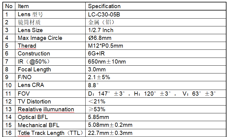
The lens barrel is generally made of metal, though plastic is also used. Metal barrels perform better in quality, high and low-temperature resistance, and other indicators. However, there are drawbacks; metal barrels can generate metal shavings when screws are tightened, posing a risk of debris entering the CMOS photosensitive area. Additionally, the hardness of metal barrels can lead to deformation of the PCB during screw installation, affecting the resolution after imaging.
The lens material is mainly of two types: glass and plastic.
Glass lenses: abbreviated as G, typically spherical in shape, processed through grinding.
Plastic lenses: abbreviated as P, typically aspherical, produced through injection molding.
In the automotive sector, glass lenses are generally used due to their excellent high-temperature resistance and scratch resistance. The surface hardness of glass is superior to that of plastic, although glass is more expensive and increases the overall thickness of the camera. However, in terms of performance requirements, glass lenses are essential, which is why a lens with 6G indicates the use of six glass elements.
Explanation of Optical Parameters of Lenses
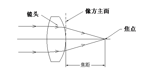
Focal Length (Focal Length or EFFL)
Refers to the distance from the main imaging surface of an optical system to the focal point, reflecting the system’s ability to focus on objects.
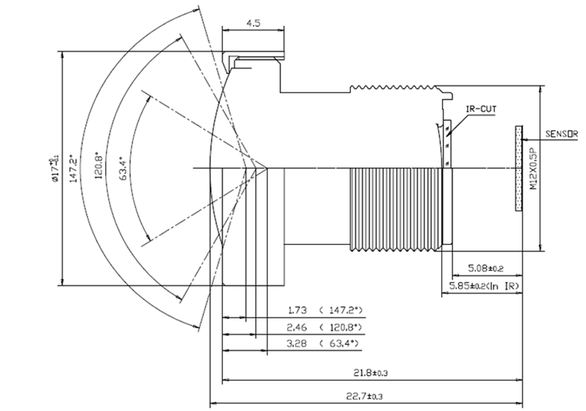
BFL Back Focal Length
Distance from the last lens surface to the imaging surface.
As shown in the above figure, this is 5.85mm;
Mechanical BFL Flange Distance
Distance from the lens barrel end (front/rear) to the imaging surface.
As shown in the above figure, this is 5.08mm±0.2mm.
Overall Length and Optical Length (TTL):
Optical length refers to the distance from the first lens surface to the image surface; while the overall length refers to the distance from the front surface (generally the barrel surface) to the image surface (e.g., sensor surface). Generally speaking, if a lens is too long or too short, its design becomes difficult, and manufacturing requires high precision; this lens’s total length is 22.7mm±0.3mm.
Relative Aperture (FNo.)
An indicator of imaging brightness in an optical system, commonly referred to as the F-number (as labeled on traditional cameras). Under the same light intensity, the smaller the value, the brighter the image surface; the larger the value, the darker the image surface. For general imaging optical systems, F2.0-3.2 is quite suitable. If a smaller F-number is required, the design becomes more challenging, the structure more complex, and manufacturing costs increase. Here, the FNo is F2.1.
Field of View (FOV):
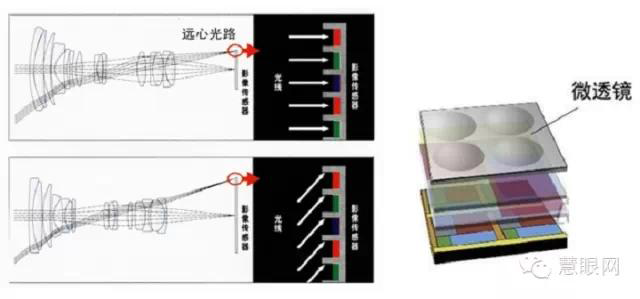
The angular range that an optical system can image. The larger the angle, the wider the imaging range of the optical system; conversely, the narrower. In actual products, there is a distinction between optical FOV and mechanical FOV; optical FOV refers to the effective FOV range that the SENSOR or film can truly image, while mechanical FOV is generally larger than optical FOV, due to other design considerations and uses, such as needing mechanical FOV to reference the size of the light aperture in the module or phone cover.
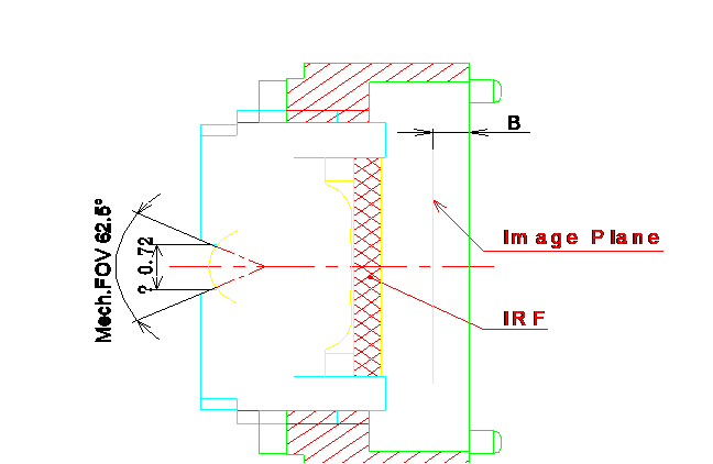
Theoretically, the larger the FOV angle, the better; for instance, in a hidden dashcam, a wider image on both sides is preferred for complete information. However, this FOV angle directly affects the camera’s distance measurement, so it should ideally be selected based on the camera’s actual application.
Optical Distortion (Opt distortion) and TV Distortion (TV distortion):
Distortion refers to the degree of image distortion of an object relative to the object itself. Optical distortion is the deformation calculated theoretically by optics. TV distortion refers to the degree of deformation when capturing actual images, with the standard for DC cameras measuring the distortion at the short edge of the sensor. Generally, optical distortion does not equal TV distortion, especially for chips with correction capabilities. Distortion is typically divided into barrel distortion and pincushion distortion, which are visually represented by funhouse mirrors, making a person look tall and thin (pincushion distortion) or short and stout (barrel distortion).
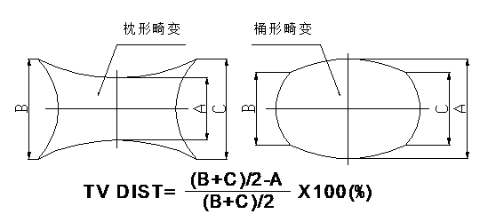
TV distortion is generally prioritized, with smaller values being better, simplifying subsequent processing by the chip. The TV distortion of this lens is less than 21%.
Relative Illumination (Relative illumination, abbreviated as RI):
It refers to the brightness at the edge of an image relative to the brightness of the central area, expressed as a ratio without units. The measured results depend not only on the optical system itself but also on the sensor used. The same lens can yield different measurement results when used with different chips.
The RI index for this in-vehicle lens is ≥53%.
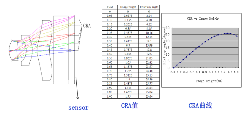
CRA Main Ray Exit Angle Through the Aperture Center Ray’s Incident Angle on the Imaging Surface
Different fields of view have different CRA values, and plotting all CRA values yields the so-called CRA curve. The CRA value shown in the diagram corresponds to the effective image height of the sensor.
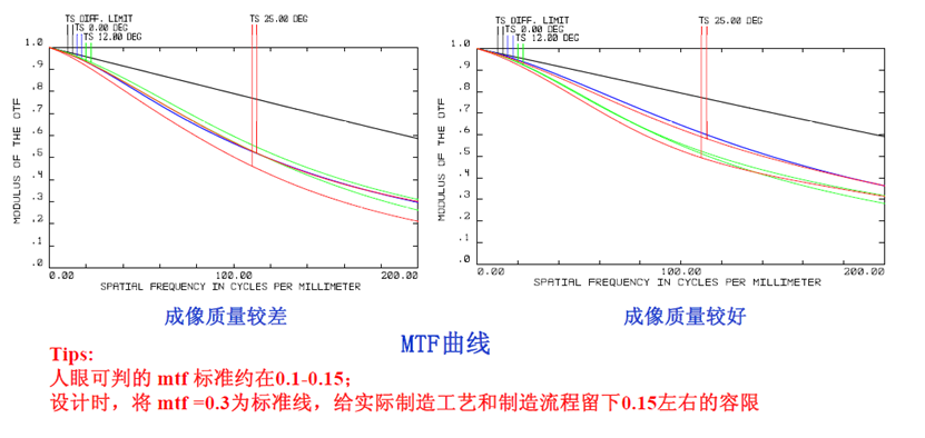
MTF:
It reflects the imaging resolution capability of an optical system to some extent. Generally, the higher the MTF, the stronger the resolution; conversely, the lower the MTF, the weaker the resolution. However, since MTF only evaluates lens resolution from one perspective, it has some limitations. Therefore, in current production, most evaluations still rely primarily on reverse projection checks for resolution.
IR Filter (Filter):
It is primarily used to adjust the color restoration of the entire system. It often varies with the chip used, as the sensitivity of the chip to different wavelength ranges of light differs. For the currently widely used CMOS and CCD photosensitive elements, it is crucial; in early CCD systems, using simple IR filters often failed to achieve good color restoration effects.
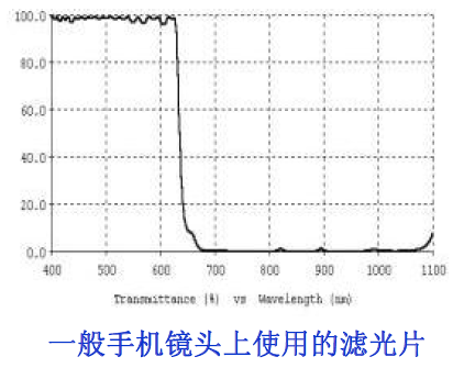
IR-Cut: The infrared light frequency with a transmittance of 50% is 650±10nm @ T=50%

Thus, we can see that the infrared filter used in in-vehicle camera lenses is generally 650nm±10nm.
The specifications of the IR coating significantly affect the lens’s color restoration capabilities. Additionally, optimizing the coating based on sensor characteristics can enhance the lens’s color restoration ability. Therefore, if a camera’s color restoration effect is poor despite software optimization, considering IR coating adjustments can be beneficial.
The lens is primarily used to focus images onto the sensor, serving as a core component. Its barriers include focal length, field of view, aperture, distortion, relative illumination, resolution, etc. Due to the harsh outdoor environment, in-vehicle lenses must exhibit good thermal stability, which is why glass is preferred over plastic materials.
The optical components industry is generally in a mature phase, with relatively high industry concentration, primarily involving traditional camera lens manufacturers. According to Yole Development, the global CR4 is around 40%-50%.
In the global market for vehicle-mounted camera lenses, Sunny Optical holds the largest market share, having entered the vehicle lens market in 2004 and achieving the highest global shipment volume since 2012. Other major manufacturers include Japan’s Seiko, Kondo, and Fujifilm.
Domestic optical lens manufacturers include Lianchuang Electronics, OFILM, Fuguang Co., and Liding Optoelectronics.
Crystal Optoelectronics (filters, protective films), OFILM (filters), and Hitec (protective films) are challenging overseas leaders, and amid the rise of new domestic forces, they are expected to ride the wave of “in-vehicle” development, leading the domestic replacement of optical components.
Camera Module Packaging
The packaging process for in-vehicle camera modules is more complex than for mobile phones, primarily ensuring driving safety and maintaining high stability during use in various driving conditions. Therefore, compared to other fields, in-vehicle cameras have higher product safety standards, production technology requirements, and greater manufacturing complexity.
From a competitive landscape perspective, the current top three companies in the global in-vehicle camera industry by market share are Panasonic, Valeo, and Fujitsu, with Panasonic holding the largest share at 20%, followed by Valeo and Fujitsu at 11% and 10%, respectively.
Current customer situations among major global camera suppliers:
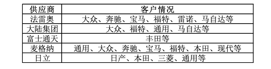 Data Source: Dongfang Securities
Key players in this field also include: Q Technology, Hikvision, BYD, United Optics, and Desay SV.
Future Improvement Needs for In-Vehicle Cameras
The significant increase in camera pixel counts not only raises performance requirements for chips but also necessitates considerations for power and thermal management. To achieve better performance, cameras require higher power supplies, making thermal management a crucial issue. Traditional cameras generally use built-in ISPs, but some industries are also using ISP-free camera modules, where data is directly transmitted to domain controllers for external ISP processing.
ISPs are the main components generating heat and increasing power consumption; some companies propose integrating ISPs into controllers for better thermal management.
For example, the solution proposed by Aptiv retains the optical lens and image sensor while moving the ISP to the corresponding controller motherboard, transmitting data via Ethernet. Many image sensor manufacturers are removing ISP modules from camera modules to limit power consumption and heat generation.
Meanwhile, ISPs integrated into specialized vision processors (SoCs) can improve image quality and process data from multiple cameras simultaneously, reducing costs.
It is believed that the costs of individual high-precision cameras will significantly decrease in the future, and as high-precision cameras become standard, there will be considerable room for overall cost reduction.
Appendix: Explanation of Tesla’s Image Recognition Principles
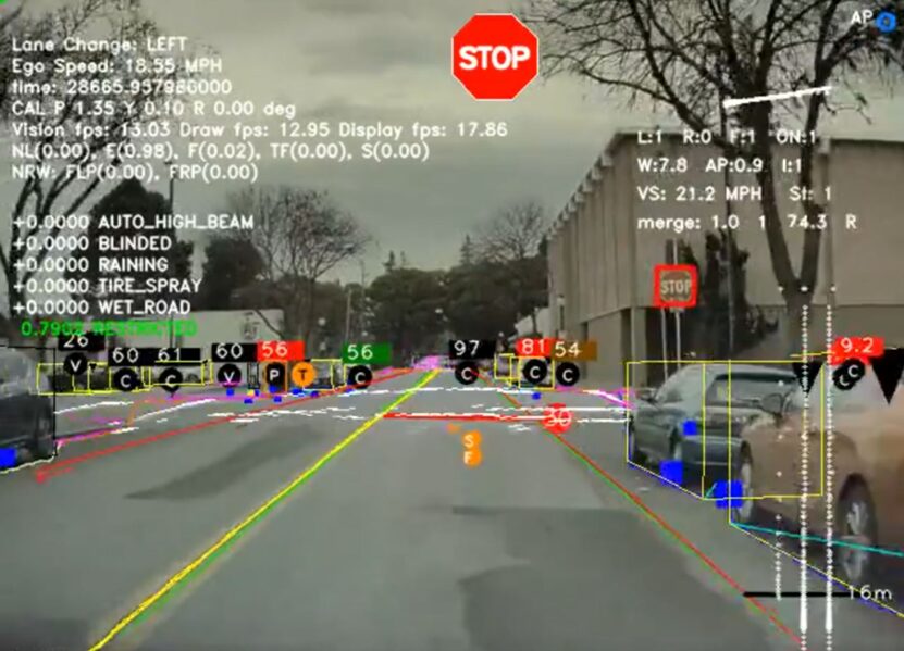
Tesla utilizes 8 cameras to recognize objects in the real world. The images captured by the cameras include pedestrians, other vehicles, animals, or obstacles, which is crucial not only for the safety of Tesla drivers but also for others. The patent states that it is essential for the cameras to accurately and timely recognize these objects.
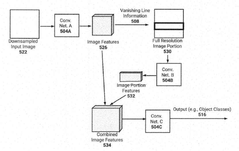
Tesla’s patented framework
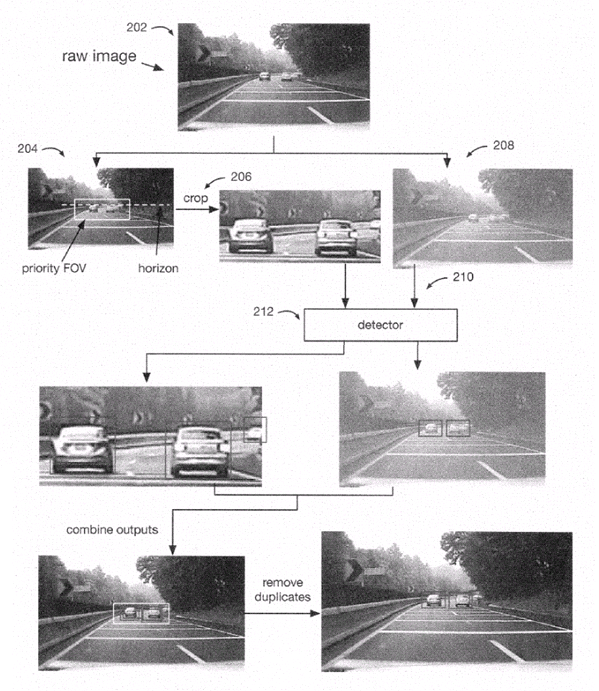
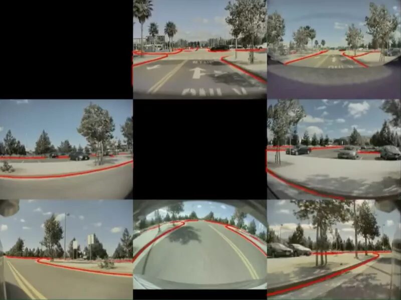
Tesla’s patented demonstration
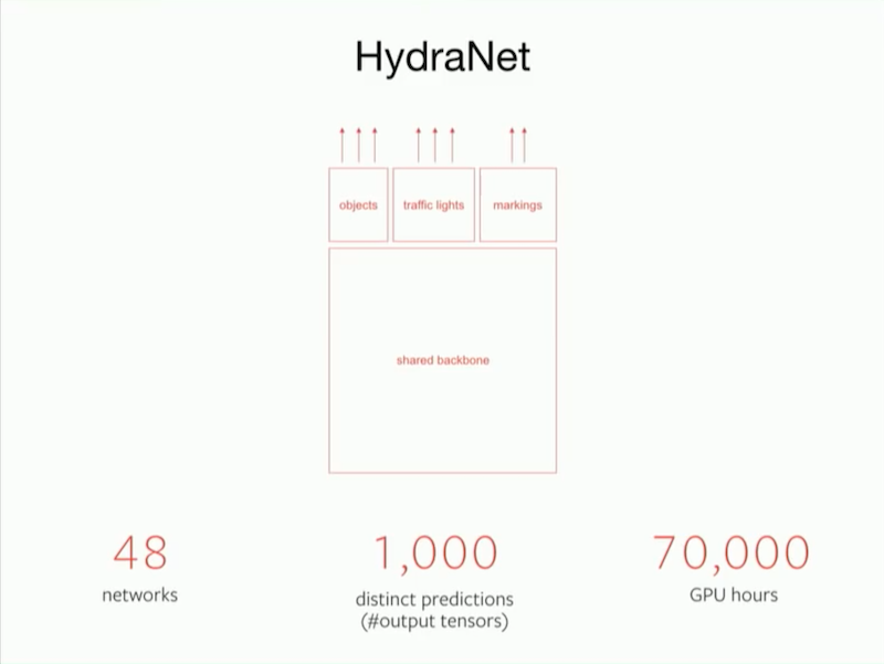
From the algorithmic code perspective, Tesla refers to its deep learning network as HydraNet. The foundational algorithm code is shared, and the entire HydraNet contains 48 different neural networks, enabling it to output 1000 different prediction tensors. Theoretically, this super network can simultaneously detect 1000 types of objects. Completing these computations is not simple; Tesla has expended 70,000 GPU hours training its deep learning model.
Although the workload is substantial, most of the work is undertaken by machines, and Tesla’s AI team consists of only a few dozen people, which is significantly smaller than the hundreds or even thousands found in other autonomous driving companies.
Completing 2D images is not particularly impressive, as cloud computing can train models, and the locally developed chips can match algorithms well. Tesla’s true strength lies in completing 3D depth information through vision and establishing high-precision maps for certain driving scenarios, such as navigating parking lots.
Tesla’s vehicles are equipped with 8 cameras, one millimeter-wave radar, and 12 ultrasonic radars to monitor the external environment, transmitting information to the autonomous driving computer in real-time.
Tesla’s external sensors
In simple terms, Tesla’s cameras, millimeter-wave radar, ultrasonic radars, and inertial measurement units record the current environmental data of the vehicle and transmit this data to Tesla’s autonomous driving computer. After performing algorithmic calculations, the autonomous driving computer sends speed and direction information to the steering rack and acceleration and braking pedals, controlling the vehicle.
However, during regular driving, the content captured by the cameras as sensors is merely 2D images, lacking depth information.
This means that although 2D images can differentiate between roads and sidewalks, they do not indicate how far the vehicle is from the “curb.” The absence of this crucial information may lead to inaccuracies in autonomous driving calculations and potential operational errors. Therefore, capturing or establishing a three-dimensional view is essential.
Tesla uses a tri-camera system, which can determine the distance to objects by comparing the images from two cameras, thereby obtaining depth information. The central processor performs perception, segmentation, detection, tracking, and other operations on the input images, outputting them to the navigation network for semantic mapping and localization, while simultaneously forming corresponding attributes for the ADAS system through target recognition.
Tesla has another impressive capability: its algorithms can predict depth information for every pixel in streaming video. In other words, as long as the algorithms are good enough, streaming video becomes clearer, and the depth information captured by Tesla’s visual sensors can even surpass that of lidar.
In practical autonomous driving applications, this algorithm can be fully utilized in two scenarios: parking and smart summon. When driving in a parking lot, the distances between vehicles are minimal, making it easy to scrape against other vehicles if the driver is not careful. For machines, navigating parking lot scenarios is even more challenging. After predicting depth information, the vehicle can quickly recognize the surrounding environment with the assistance of ultrasonic radars, making parking much smoother.
After predicting depth information, this information is displayed on the vehicle’s display and directly participates in controlling steering, acceleration, and braking actions. However, steering, acceleration, and braking strategies do not have fixed rules and are somewhat flexible. Therefore, there is no absolute best driving strategy in autonomous driving, only better ones.
Source: AIOT Big Data
Editor: Zhang Jingwei
Reviewer: Yan Hairong