Optimization Design of Mold Cooling Channels with Lattice Structures
Chuzhong, Zhao Caoxi, Kang Hui,
Ni Zihan, Li Zhitong, Zhang Jicong
(School of Mechanical Engineering, Shanghai University of Applied Technology, Shanghai 201418)
First Author:
Chuzhong (1967—), Male, Associate Professor, Engaged in mold CAD/CAM research, [email protected]
Corresponding Author:
Zhao Caoxi (1999—), Male, Master’s Student, Engaged in industrial research on conformal cooling channels, [email protected]
DOI:10.19491/j.issn.1001-9278.2024.11.019
Citation:
Chuzhong, Zhao Caoxi, Kang Hui, et al. Optimization design of mold cooling channel with lattice structure[J]. CHINA PLASTICS, 2024, 38(11):114-117.
CHU Zhong, ZHAO Caoxi, KANG Hui, et al. Optimization design of mold cooling channel with lattice structure[J]. CHINA PLASTICS, 2024, 38(11):114-117.
0
Introduction
For deep cavity precision plastic parts, conformal cooling channels are often used for cooling. Although conformal channels have good cooling effects, they have certain limitations in local cooling. Utilizing conformal cooling channels with lattice structures can improve cooling efficiency. Tan Chaolin designed a self-supporting structure for conformal cooling channels and found that the support rods increased the heat exchange area, reducing product cooling time by approximately 22.2%; Oh and others designed a spiral gyroid lattice structure cooling system, reducing cooling time by 40% while improving cooling uniformity; Kanbur and others added a body-centered cubic unit cell in the conformal channel, reducing cooling time by 62.9% and improving cooling uniformity. Additionally, the choice of cross-section also affects cooling efficiency. Rectangular cross-sections provide better cooling for deep cavity parts compared to circular cross-sections, but their printability is poor. Therefore, a racetrack-shaped cross-section was chosen to meet both cooling efficiency and printing process requirements.
This paper focuses on deep cavity plastic parts, using Moldex software for mold flow simulation to design a lattice structure at the top of the core to improve the local cooling effect of the mold core. Then, Ansys is used for static analysis of the mold core, which meets the strength requirements. Finally, the mold core is produced using 3D printing SLM technology and experimentally validated.
1
Design of Conformal Cooling Channels
The plastic part is a spray-type high-end cosmetic cap, made of acrylonitrile-butadiene-styrene copolymer (ABS), precision grade MT3, surface roughness Ra0.4. The design parameters of the conformal channel include the dimensions a and b of the racetrack-shaped cross-section, the spacing (p) between adjacent channels, and the distance (s) from the channel center to the core wall, with specific parameter values of a=2.05 mm, b=3.8 mm, p=12.85 mm, s=4 mm, and the arrangement of the channels is spiral. The shape of the plastic part, racetrack-shaped cross-section, and channel layout are shown in Figure 1.
Figure 2 Tridiametral Unit Cell
2
Design of Lattice Structures
Although conformal channels have good cooling effects, the top position of the core has limited space, restricting the layout in that area, which in turn affects cooling efficiency and can easily lead to uneven cooling. To improve the temperature distribution of the mold, a lattice structure is used at the top of the core. The lattice structure used in this paper is relative to the field of additive manufacturing. Generally, its purpose is to achieve lightweight parts by replacing solid structures with lattice structures, and it has certain structural strength that does not affect the use of the part. In the application of conformal channels, its main purpose is to solve the hotspot problem of conformal channels by filling the local hotspot areas with lattice structures instead of conformal channels. Water can flow through the gaps in the lattice structure to carry away heat, making cooling more uniform. The basic unit of the lattice structure is the unit cell, which consists of connecting nodes and connecting rods between the nodes, and the unit cell is replicated in three-dimensional space to form the lattice structure. The connecting rods can increase the heat exchange area, enhance cooling effects, and the secondary flow generated can further enhance cooling. However, to ensure sufficient gaps for cooling water to pass through, a unit cell with a high porosity—tridiametral unit cell (Figure 2)—is used, with edge lengths L1=L2=L3=6 mm and the diameter (d) of the connecting rods being 1 mm, as shown in Figure 2.
Figure 2 Tridiametral Unit Cell
Since the lattice structure area is an internal cavity, it can lead to difficulties in powder cleaning. If powder residue is present in the cooling system, it may lead to powder adhesion and dirt formation during heat treatment, blocking the water channels. Therefore, the area below the lattice needs to be set as a slope to gather the powder, while a cleaning hole is set in the center to allow the powder to flow out. The slope angle is determined based on the repose angle of the powder, which is the acute angle formed between the slope of the powder pile and the horizontal plane at static equilibrium. When the slope angle equals the repose angle, the powder can slide freely. Generally, the repose angle of metal powders used in 3D printing is between 30 ° and 40 °. Considering that the cleaning method involves blowing and sucking from the inlet and outlet of the channel, the slope angle can be less than the repose angle. This paper takes 20°, and the structure is shown in Figure 3, where H is the height of the lattice area, and θ is the slope angle. The filled lattice structure is shown in Figure 4. During cleaning, air is blown from the inlet and outlet of the double spiral channel, and the powder is sucked from the cleaning hole, as shown in Figure 5, which is the final core structure.
Figure 3 Cleaning Structure
Figure 4 Lattice Structure
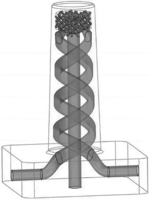
Figure 5 Final Core Structure
3
Simulation Results and Analysis
3.1
Mold Flow Analysis Results
Using Moldex for mold flow analysis, based on material properties, the process parameters are set to mold temperature 50 ℃, melt temperature 205 ℃, cooling water temperature 25 ℃, with other parameters default. The temperature results of the mold core are shown in Figure 6.
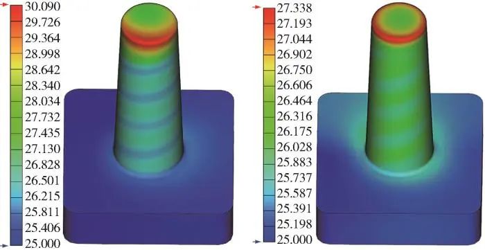
Figure 6 Mold Core Temperature
Three points are selected radially on the upper surface, labeled as points 1, 2, and 3, and two points are selected on the side, labeled as points 4 and 5. The surface temperatures of the core structures before and after adding the lattice structure are compared, as shown in Figure 7.
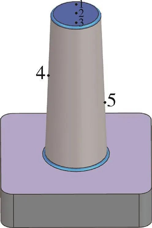
Figure 7 Selection of Temperature Points
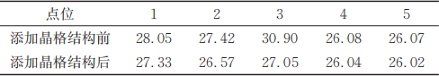
The temperature distributions of points 4 and 5 on the core structures before and after adding the lattice structure are basically the same. The uneven temperature mainly occurs on the upper surface of the core. The maximum surface temperature of the mold core with the conformal channel structure before adding the lattice structure is 30.90 ℃, and the minimum is 27.42 ℃, with a temperature difference of 3.48 ℃; after adding the lattice structure, the maximum surface temperature is 27.33 ℃, and the minimum is 26.57 ℃, with a temperature difference of 0.76 ℃. The latter improves the temperature distribution uniformity by 78%, with specific results shown in Table 1.
Table 1 Temperature Distribution of Water Channels Before and After Adding Lattice Structure
3.2
Static Structural Analysis Results
Using the FEA interface of Moldex3D, this function can export the grid of the mold core and the pressure at multiple grid nodes as a “.cdb” file. Generally, the maximum pressure moment in the cavity is at the moment of the speed/pressure transition point. The pressure results at this moment are imported into Ansys for static structural analysis. The upper surface 1, side surface 2, bottom slope 3, spiral channel wall 4, and cleaning hole 5 of the lattice structure area are selected as analysis surfaces, as shown in Figure 8. The stress analysis results are shown in Figure 9, with a maximum stress of 613.05 MPa on the five surfaces. The material of the mold core is Corrax powder, with a yield strength of 1,579 MPa, meeting the strength requirements.
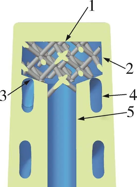
Figure 8 Selection of Analysis Surfaces
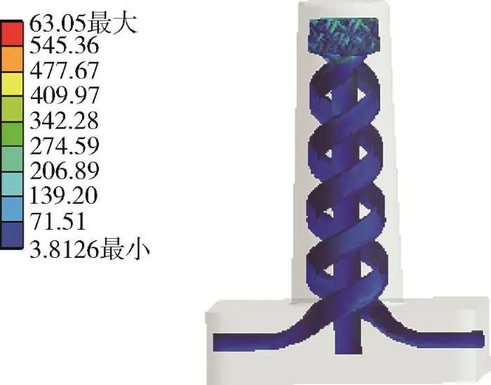
Figure 9 Stress Analysis Results
4
Core Printing and Verification
The optimized water channel scheme’s core was produced using 3D printing SLM technology, with good printing results, no defects on the surface, and normal powder cleaning, as shown in Figure 10.
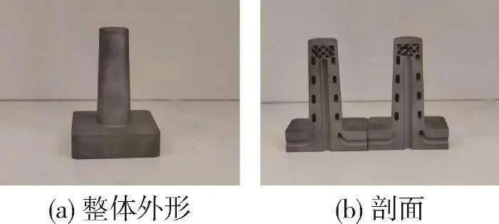
Figure 10 3D Printed Mold Core
Using K-type thermocouples and Max6675 signal converter modules to measure temperatures at the five points from the previous section, the experimental setup is shown in Figure 11. The mold core is heated to 205℃, with a water flow rate of 2L/min and water temperature of 20℃. Temperatures at the five points are detected, with the final results shown in Figure 12. An Arduino Mega2560 development board is used to collect temperature information and transmit it to a computer, with results shown in Figure 12. The experimental results indicate (Figure 12) that during the cooling process, the temperature difference at the five points is within 7℃, with the temperature difference at the three points on the top of the core within 3℃. The temperature distribution is relatively uniform, and at the end of cooling, the temperatures at each point differ from the simulated results by less than 2.5℃. The experimental and simulated results match well, indicating that the mold core has good temperature distribution uniformity.


5
Conclusion
(1) The lattice structure provides better cooling effects for the upper part of deep cavity cores compared to traditional conformal cooling channels, demonstrating that the lattice structure has good heat transfer capabilities and can achieve a more uniform temperature distribution in local areas, with temperature distribution uniformity improved by 78%, verified by experiments;
(2) The lattice structure has good structural strength, and the maximum stress in critical areas above the core meets strength requirements, satisfying the mold’s usage requirements;
(3) For some local areas where designing conformal channels is inconvenient, lattice structures can be used to fill those areas to improve cooling effects.


Long press the QR code to read the full text
Editor: Hu Bai
Layout: Bai Tianmeng
Review: Liu Xue


“China Plastics” is a national scientific and technological journal approved by the National Science and Technology Commission and the National Press and Publication Administration. It is a monthly publication sponsored by the China Plastics Processing Industry Association, Beijing Technology and Business University, and the Light Industry Plastics Processing Application Research Institute.“China Plastics” is a national core journal, a dual-effect journal of the Chinese Academy of Sciences, a core journal indexed by the American Chemical Abstracts (CA), a source journal for the statistical analysis of Chinese scientific papers, and a core journal of the Chinese Science Citation Database (CSCD), and has won the third National Journal Award.“China Plastics” is published on the 26th of each month, with public distribution at home and abroad, CN11-1846/TQ, ISSN1001-9278.
For submissions, please log in to the official website:
www.plaschina.com.cn
www.chinaplasticsjournal.com
For subscriptions, please contact the editorial department:
010-68985541

Scan to follow us
China Plastics Editorial Department