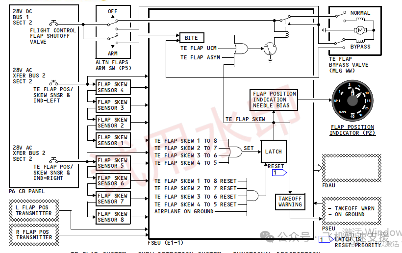
The FSEU controls the flap position indicator (gauge) based on data from the flap position sensors. The data from the sensors serves as input values for flap asymmetry. When the angle difference (scissor difference) between the two flap position sensors exceeds 9°, it triggers a flap asymmetry alert. The flap position sensor is also used for detecting flap deflection. When a flap is deflected, the left flap deflection sensor compares to the left flap position sensor. When the angles match, deflection occurs on the right wing, and when the angles do not match, deflection occurs on the left wing. If the deflection sensor angle exceeds that of the position sensor, the FSEU will extend the flap by 15°; conversely, it will retract by 15°.
Installation and Adjustment of Flap Position Sensor
Before removing the flap position sensor, the hydraulic system must be used to set the flap to position 40 on the flap handle. At this point, although the hydraulic system cannot release the flap any further, it is not fully extended, and manual operation is required to fully extend the flap.
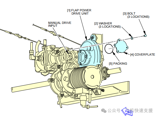
On the front wall of the wheel well, the flap PDU can be manually operated. After executing the rear edge flap limit motion, approach the flap PDU, remove the cover, and use a 3/8 connector to rotate the PDU. Rotate clockwise facing the cover to release the flap and counterclockwise to retract it. Note that the torque must not exceed 350 pounds; otherwise, the mechanism may be damaged.
After fully extending the flap, the flap position sensor that needs to be replaced can be removed.
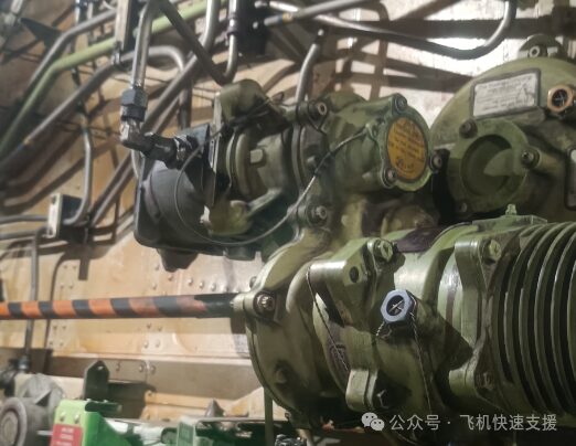
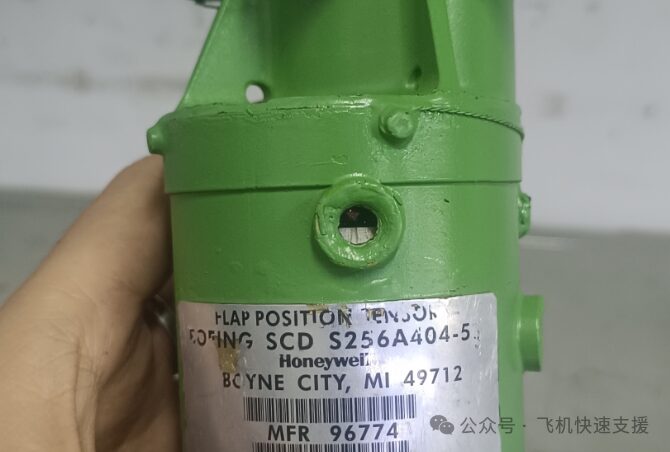
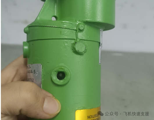
Before installing the new part, check that both indicators on the body meet the requirements. One indicator window should show a white dot (as in the second image, indicating that the part has been calibrated before leaving the factory and can be used), and another indicator window should show a scale line corresponding to a triangle (as in the first image, indicating that this sensor is at its limit position. If the flap is at its limit position, adjustment will likely not be necessary to meet the manual requirements). If there is no white dot, a new part must be obtained. If the triangle does not appear, the shaft can be manually rotated until the triangle appears.
 Use hydraulics to retract the flaps and ensure that the gauge pointer returns to the UP white range (preferably on the scale line). However, if the flap scissor difference exceeds 9°, it will trigger a flap asymmetry alert. During the retraction of the flaps, monitor the angle value changes of the flap position sensors on both sides on the FSEU and check for significant differences in angle values. If the angle values are basically the same, proceed with the final test.
However, the smooth operation is generally not satisfactory, and the following situations may occur: manually driving the PDU is difficult, and the flaps cannot be extended to the limit position; new parts do not have the indicating triangle, leading to a mismatch between the sensor and the actual position of the aircraft during new part installation. In this case, the sensor needs to be readjusted, and this method can resolve the issues.
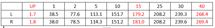
Extend the flaps to more than 40° (40° is acceptable) without needing to reach the limit position, directly replace the new sensor without worrying about whether the actual position matches the sensor position. After installation, retract the flaps (hydraulics can be used; if the angle difference is too great, the flap bypass valve will automatically go to bypass position, and hydraulics will not be usable. In this case, use the backup flap retraction operation). Read the angle values on the FSEU (operation: ON/OFF-OTHER FUNCTIONS?- I/O MONITOR?-SYNCRO INPUTS? -L FL POS, or R FL POS). At this point, the in-flight indication and FSEU will synchronize. If the angle difference is too large, a significant scissor difference will appear. Display the FSEU to the page showing the values of the replaced sensor. Use the backup operation to extend the flap until the new sensor shows 180.0 ±0.4. At this time, the new sensor has been set to around 180°, but checking another sensor will reveal a large difference due to the flap’s actual position not being at 180°. At this point, remove the new part (do not move the shaft!!!), move the flap handle to 15 units (the flap angle value corresponding to 15 units is 180°). After applying pressure, the flap will move to the corresponding position of 15 units (sometimes hydraulic failure may occur due to the angle difference between the two sensors exceeding 9°, causing the flap bypass valve to automatically bypass; recovery is possible). At this point, the flap’s corresponding position matches the new sensor’s position. Without moving the shaft, reinstall the flap position sensor. Calibration is now complete. Retract and extend the flaps, and check the values of the two sensors on the FSEU, recording the values without the handle position. The manual provides the angle values for the handle at UP, 15 units, and 40 units as shown in the figure below.
Use hydraulics to retract the flaps and ensure that the gauge pointer returns to the UP white range (preferably on the scale line). However, if the flap scissor difference exceeds 9°, it will trigger a flap asymmetry alert. During the retraction of the flaps, monitor the angle value changes of the flap position sensors on both sides on the FSEU and check for significant differences in angle values. If the angle values are basically the same, proceed with the final test.
However, the smooth operation is generally not satisfactory, and the following situations may occur: manually driving the PDU is difficult, and the flaps cannot be extended to the limit position; new parts do not have the indicating triangle, leading to a mismatch between the sensor and the actual position of the aircraft during new part installation. In this case, the sensor needs to be readjusted, and this method can resolve the issues.
Extend the flaps to more than 40° (40° is acceptable) without needing to reach the limit position, directly replace the new sensor without worrying about whether the actual position matches the sensor position. After installation, retract the flaps (hydraulics can be used; if the angle difference is too great, the flap bypass valve will automatically go to bypass position, and hydraulics will not be usable. In this case, use the backup flap retraction operation). Read the angle values on the FSEU (operation: ON/OFF-OTHER FUNCTIONS?- I/O MONITOR?-SYNCRO INPUTS? -L FL POS, or R FL POS). At this point, the in-flight indication and FSEU will synchronize. If the angle difference is too large, a significant scissor difference will appear. Display the FSEU to the page showing the values of the replaced sensor. Use the backup operation to extend the flap until the new sensor shows 180.0 ±0.4. At this time, the new sensor has been set to around 180°, but checking another sensor will reveal a large difference due to the flap’s actual position not being at 180°. At this point, remove the new part (do not move the shaft!!!), move the flap handle to 15 units (the flap angle value corresponding to 15 units is 180°). After applying pressure, the flap will move to the corresponding position of 15 units (sometimes hydraulic failure may occur due to the angle difference between the two sensors exceeding 9°, causing the flap bypass valve to automatically bypass; recovery is possible). At this point, the flap’s corresponding position matches the new sensor’s position. Without moving the shaft, reinstall the flap position sensor. Calibration is now complete. Retract and extend the flaps, and check the values of the two sensors on the FSEU, recording the values without the handle position. The manual provides the angle values for the handle at UP, 15 units, and 40 units as shown in the figure below.
 Compare the newly obtained data to verify the calibration results. The results of this calibration are effective.
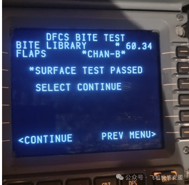
1. Flight Control Computer (FCC) Built-In-Test Equipment (BITE) library test NO.34
Complete the test on the CDU:
INDEX—MAINT—DFCS—EXTENDED MAINTENANCE—BITE LIBRARY TESTS—CHANNEL A (select left flap position sensor A, right side select B)—RUN SELECT LIBRARY TESTS—FLAP
2. Flap Sensor (TASK 27-32-00-740-803)
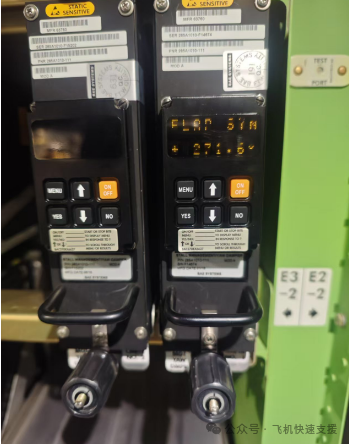
Complete the test on the SYMD computer. The SYMD computer will synchronize the display of the position sensor’s angle values.
GROUND TEST—ANALOG INPUTS?—FLAP SENSOR? —FLAP DET (flap detent position), FLAP SYN (flap synchro angle)
Conclusion
The calibration of the 737 flap position sensor essentially involves first ensuring that the sensor itself is in the limit position, and then adjusting the actual position of the flap to the limit position to install the sensor. At this point, the flap and sensor will match. Similarly, fixing the sensor position at a special angle and then adjusting the actual position of the flap to that angle can also complete the calibration. The manual provides the angle values for the handle positions UP, 15, and 40, so calibration can be approached from these three angles. The UP position cannot be approached, so both 15 and 40 can complete the calibration. There is no need to be limited to the manual, as the difficulties encountered in practice are far more than what can be solved by simply removing and installing as stated in the manual.