1Introduction
Keil5, as a classic integrated development environment, has become the preferred tool for electronics enthusiasts to handle various series of chips due to its powerful code editing, debugging, and project management capabilities. Creating a new project, as the first step in the development process, directly affects the smoothness of subsequent code writing and debugging optimization. This article will take the STM32F103 series chips as an example to systematically explain how to complete the project setup from scratch in Keil5, covering key steps such as file structure planning, chip model selection, and startup file configuration, helping developers avoid common configuration pitfalls and quickly establish a standardized development framework.
All files for the STM32 series chips can be downloaded from the ST official website:
https://www.st.com
2Steps to Create a New Project in Keil501
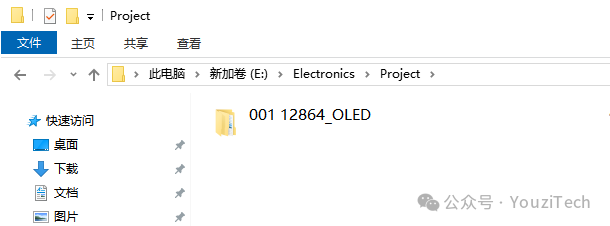
Create a new folder in the designated directory to centrally store project files. Note that the folder name should ideally relate to the project’s content for easier searching and management.
02
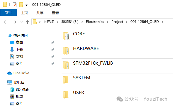
In the newly created folder, create five subfolders:
CORE: Stores the low-level files of the M3 core and STM32 startup files.
HARDWARE: Stores peripheral driver code.
STM32F10x_FWLIB: Stores the official standard peripheral library files.
SYSTEM: Stores the core driver files that build the project.
USER: Stores user-written program files.
 03
03
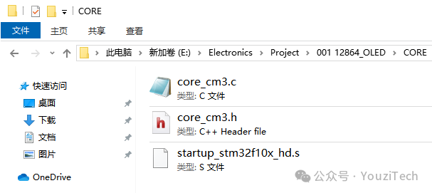
Copy the core_cm3.c and core_cm3.h files provided by the official library into the CORE folder. These are the low-level files for the ARM Cortex-M3 processor core, containing core functionalities such as register operations and interrupt management.
Then, based on the chip used in the project, copy the corresponding startup files into the CORE folder. The startup files are used for initializing hardware, configuring the interrupt vector, setting the system clock, and entering the main function, among other critical operations. The files startup_stm32f10x_hd, startup_stm32f10x_md, and startup_stm32f10x_ld correspond to chips with different FLASH capacities.
hd: Suitable for 256KB ≤ FLASH, such as the STM32F103xx series.
md: Suitable for 64KB ≤ FLASH ≤ 128KB, such as the STM32F101xx series.
ld: Suitable for FLASH ≤ 32KB, such as the STM32F100xx series.
 04
04
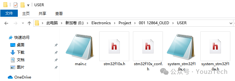
Create a new main.c file in the USER folder. Copy the official files stm32f10x.h, stm32f10x_conf.h, system_stm32f10x.c, and system_stm32f10x.h into the USER folder.
stm32f10x_conf: This file serves as a centralized configuration hub for peripheral drivers, controlling the available peripheral libraries in the project by including or excluding peripheral header files.
system_stm32f10x: This file is responsible for system-level initialization, including clock configuration and interrupt vector table positioning.
 05
05
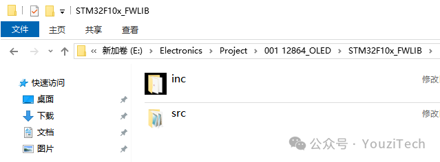
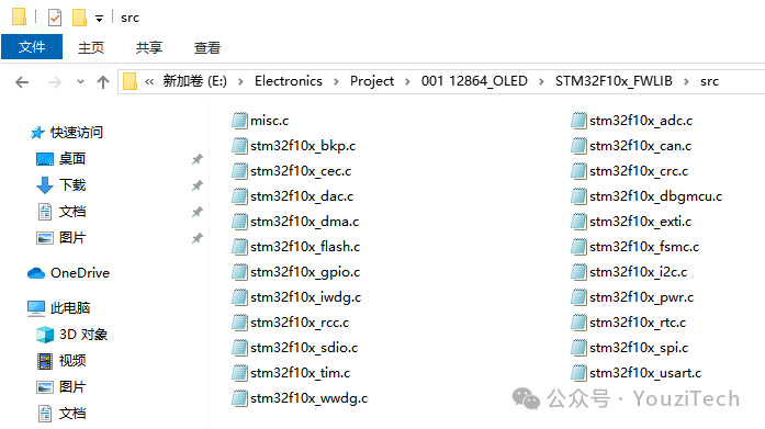
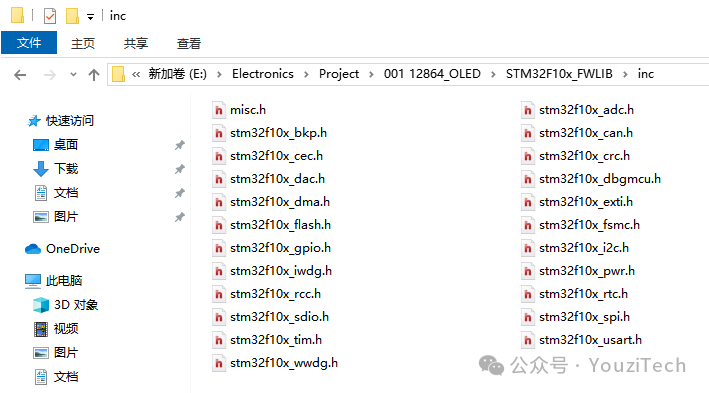
Copy the stm32f10x firmware library into the STM32F10x_FWLIB folder. This software development package includes low-level drivers, peripheral configurations, example codes, etc., primarily used to simplify the development process and facilitate user usage.
The firmware library can be downloaded from the ST official website:
https://www.st.com/en/microcontrollers-microprocessors/stm32-32-bit-arm-cortex-mcus.html#
 06
06
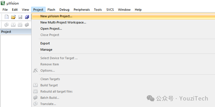
Open the Keil5 software, click on the “Project” menu, and select to create a new project.
 07
07
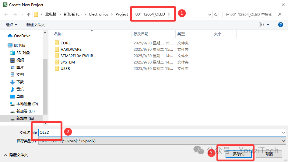
In the pop-up window, select the path to place the project root directory, define the project file name, and click “Save”.
 08
08
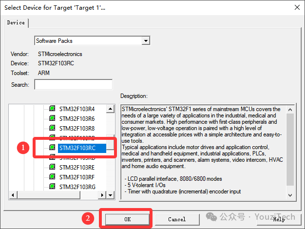
Select the chip model used in the project in the device window and click “OK”. If the chip model cannot be found, you need to download the development kit in advance, such as the various series PACK packages from the STM32 official website.
 09
09
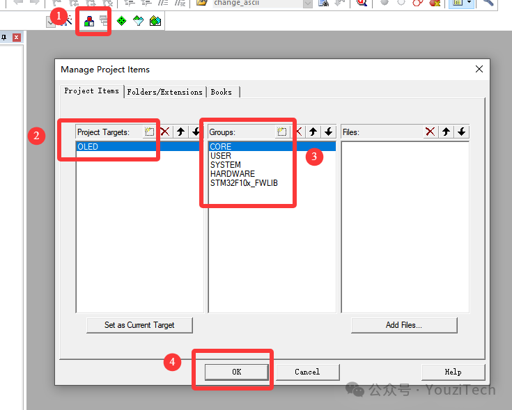
Click the Manage Project Items icon in the menu bar to change the file names and add new files in the Project Targets and Groups options. The names should correspond to the folder names created in step two for easier management.
 10
10
Click the Options for Target icon in the menu bar, select the Output option, and check the “Create HEX File” option. This way, a hex file will be automatically generated in the Objects folder after the project is successfully compiled.
 11
11
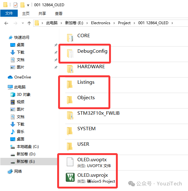
At this point, several files will be automatically generated in the project root directory. The DebugConfig folder is used to store debugging configuration files; the Listings and Objects folders are used to store files generated during the compilation process; the other two files are related to Keil, where the file with the uvoptx suffix stores configuration related to project settings, and the file with the uvprojx suffix contains the structure and other information of the entire project.
 12
12
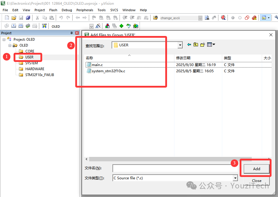
Double-click the USER directory to add the main.c file from the directory. If needed, add files like system_stm32f10x.c as well.
 13
13
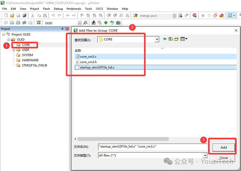
Double-click the CORE directory to add the core_cm3.c and startup_stm32f10x_hd.s files from the directory.
 14
14
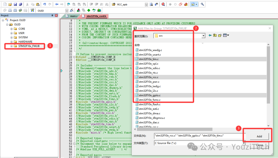
Double-click the STM32F10x_FWLIB directory to add the required driver files based on the project needs.
 15
15
In the SYSTEM folder, add core driver files such as delay, sys, uart, etc., based on project requirements. Follow the previous steps to add them to the Keil5 software project.
 16
16
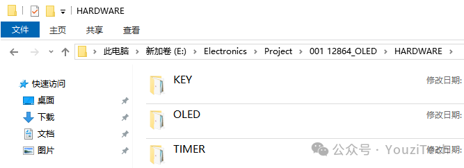
In the HARDWARE folder, add peripheral driver files such as key, oled, timer, etc., based on project requirements. Follow the previous steps to add them to the Keil5 software project.
 17
17
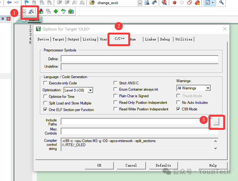
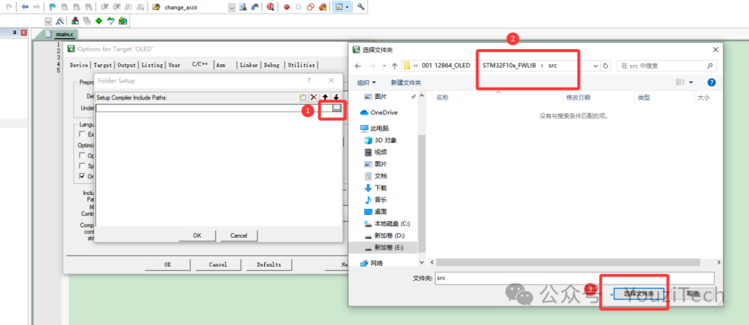
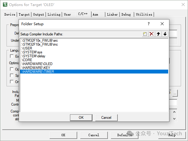
After adding, you also need to configure the path list for the source file directories. Click the Options for Target icon, select the C/C++ option, and configure the Include Paths. In the pop-up window, add the directory paths for all project files.
 18
18
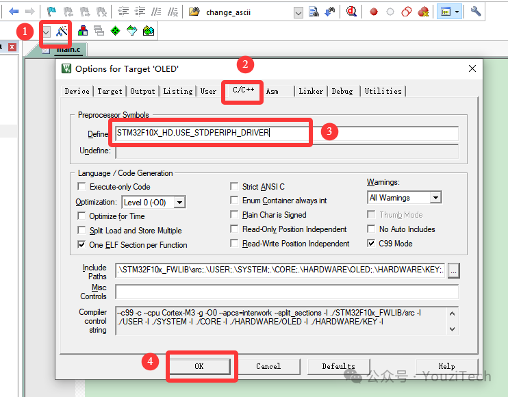
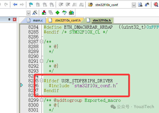
After adding the directory paths, fill in the Define in the C/C++ options with “STM32F10X_HD,USE_STDPERIPH_DRIVER”.
STM32F10X_HD: This is mainly used to distinguish between different capacities of STM32 chips and ensure that the compiler loads the corresponding register configurations and interrupt vector tables based on the specific model.
USE_STDPERIPH_DRIVER: This macro is used to enable the standard library’s peripheral driver program. If the file stm32f10x_conf.h is used, this macro needs to be added.
 19
19
Add the main function in the main.c file, write the program code, and click the Build icon in the menu bar to compile the program. If there are warnings and errors, double-clicking the error message will take you to the error location.
 3Conclusion
Establishing an STM32 project requires attention to detail and verification. Common errors include missing library files and clock configurations. By conducting multiple tests and verifications, these can be gradually avoided. When starting to establish a project, begin with simple test programs and then add more complex functionalities to gradually improve. Comments in the code are essential for later reviewing the program code, allowing for quicker and more accurate understanding. Finally, it is also important to regularly back up project files to prevent bugs and restore original files, mitigating other risks.