Table of Contents
1. GPIO Interrupt Related Registers
2. Code Implementation of PA1 Input Interrupt
3. Summary & Precautions
01
—
GPIO Interrupt Related Registers
In the previous STM32 series tutorial (3): Understanding STM32’s GPIO, several basic registers of GPIO were discussed. However, to use the interrupt functionality, it is necessary to utilize the GPIO multiplexing capability and the STM32 interrupt mechanism. The functional block diagram of external interrupts is as follows:
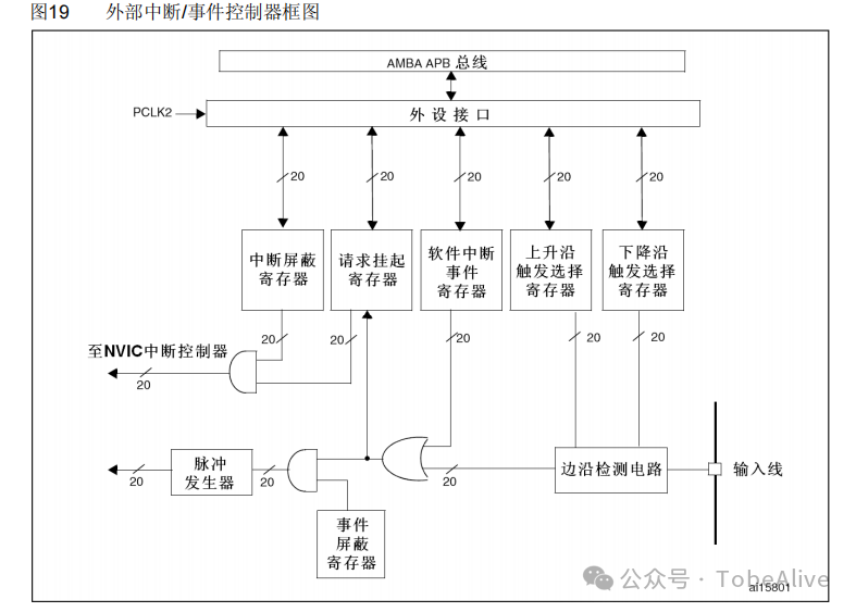
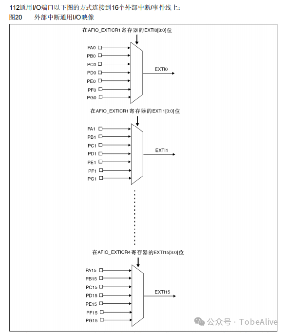
There are 20 interrupt lines, of which 16 are external interrupt event lines, as shown in the following block diagram:
Below are several registers related to configuring GPIO interrupt functionality:
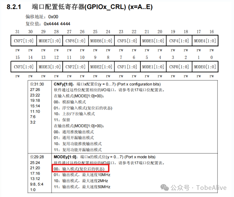
The Port Configuration Register bits [0:3] need to be configured to input mode (PA1 pin) to enable the basic input functionality of the pin.
The External Interrupt Configuration Registers for STM32F103 consist of four registers (EXTI1~EXTI4). The configuration of these four registers is the same, differing only in the corresponding GPIO pin groups (PX0~PX15).
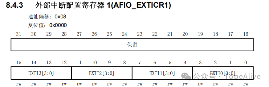
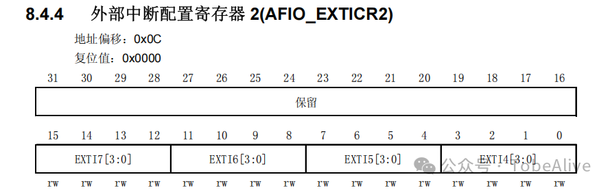
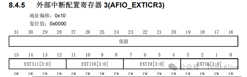
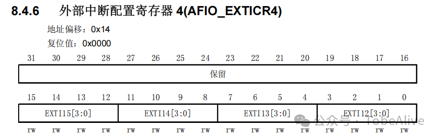
The configuration of bits [3:0] is as follows:
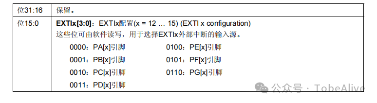
For example, to configure the PA1 pin, the bits [7:4] of register 1 need to be configured, as shown in the following image:
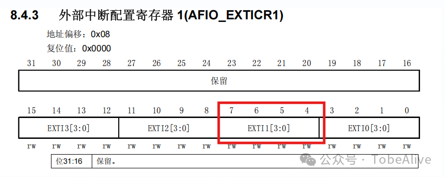
The interrupt mask register needs to unmask the EXTI1 interrupt line, as shown in the following image:
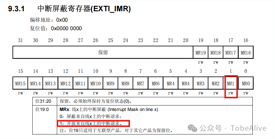
The first bit needs to be set to ‘1’
Rising Edge Trigger Register and Falling Edge Trigger Register
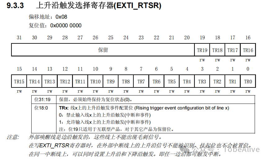
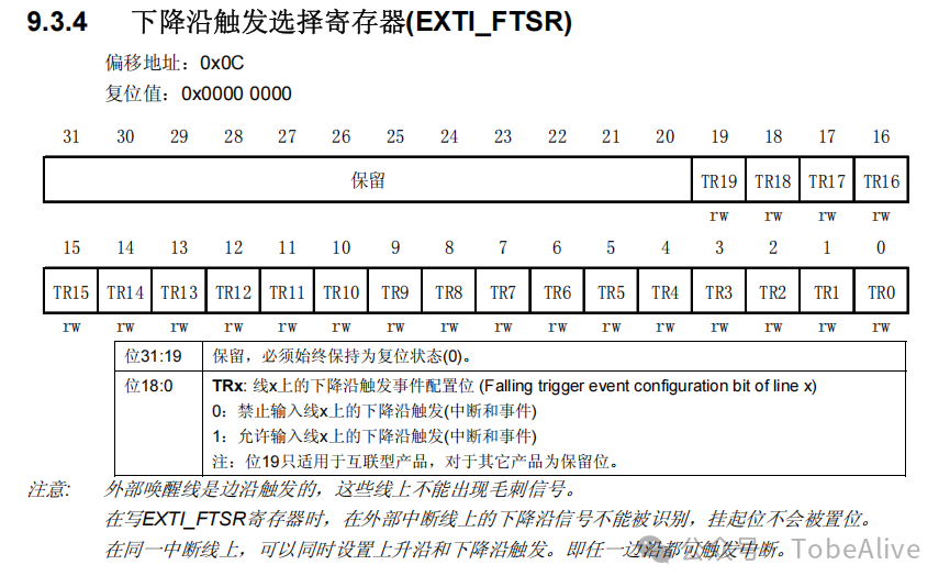
For PA1, both rising and falling edges can be configured as interrupt trigger events. What are rising and falling edges? Well, let’s illustrate (abstract version):
Rising Edge Falling Edge
1 ____ ____
0 ____| |______
It means that >_<
The Pending Register bit indicates the occurrence of a related interrupt event. When an interrupt event occurs, this bit is set to ‘1’.
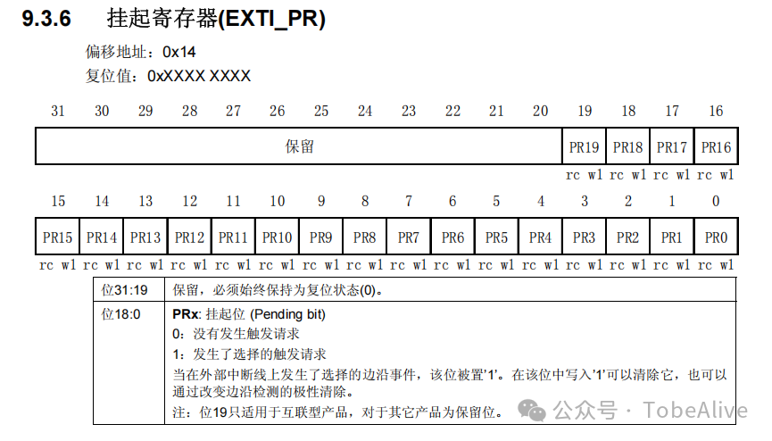
The NVIC Register of STM32 is related to the Cortex-M3 core and will be explained later (The NVIC register is located in the System Control Space (SCS) of the Cortex-M3 core, starting at address 0xE000E100. The specific offset of each register is in the core_cm3.h header file).
A brief introduction to several key registers is as follows:
The Interrupt Set-Enable Registers (ISERx) are used to enable specified interrupt sources.
The Interrupt Clear-Enable Registers (ICERx) are used to disable specified interrupt sources. The Interrupt Set-Pending Registers (ISPRx) are used to manually set the pending state of specified interrupt sources. When the interrupt condition is met but the CPU has not yet responded, the interrupt is in a pending state (the hardware will also automatically set the pending bit). Setting the pending bit will force the CPU to respond to this interrupt later (if enabled and priority allows). The Interrupt Clear-Pending Registers (ICPRx) are used to manually clear the pending state of specified interrupt sources. Typically, after processing the interrupt reason in software, the pending bit needs to be cleared to prevent the interrupt from being repeatedly responded to (although the hardware usually clears the pending bit at the entry of the interrupt service routine, sometimes manual intervention is needed). The Interrupt Active Bit Registers (IABRx) are used to query whether a specified interrupt source is currently active (i.e., the CPU is executing the service routine for that interrupt and has not yet exited). The Interrupt Priority Registers (IPRx) are used to set the priority of each maskable interrupt source.
02
—
Code Implementation of PA1 Input Interrupt
1. Write GPIO Initialization Code
void MX_GPIO_Init(void) {
  GPIO_InitTypeDef GPIO_InitStruct = {0};

  __HAL_RCC_GPIOA_CLK_ENABLE();  // Enable GPIOA clock

  // Configure PA1 as interrupt input
  GPIO_InitStruct.Pin = GPIO_PIN_1;
  // Falling edge trigger
  GPIO_InitStruct.Mode = GPIO_MODE_IT_FALLING;
  // Pull-up on pin
  GPIO_InitStruct.Pull = GPIO_PULLUP;
  HAL_GPIO_Init(GPIOA, &GPIO_InitStruct);

  // Configure NVIC
  HAL_NVIC_SetPriority(EXTI1_IRQn, 0, 0);  // Set priority
  HAL_NVIC_EnableIRQ(EXTI1_IRQn);          // Enable interrupt channel
}
2. Write Interrupt Callback Function
// EXTI1 Interrupt Service Function
void EXTI1_IRQHandler(void) {
  HAL_GPIO_EXTI_IRQHandler(GPIO_PIN_1);  // Call HAL interrupt handler
}

// Interrupt callback function
void HAL_GPIO_EXTI_Callback(uint16_t GPIO_Pin) {
  if(GPIO_Pin == GPIO_PIN_1) {
    // Interrupt handling logic
  }
}
03
—
Summary & Precautions
GPIO interrupts are generally triggered on the falling edge for button logic processing; do not use blocking operations or long CPU-occupying logic in the interrupt callback function.