01
Inside the MCS-51 microcontroller, there is a high-gain inverting amplifier, where the input is XTAL1 and the output is XTAL2. The oscillation circuit formed by this amplifier and the clock circuit together constitute the clock mode of the microcontroller.Depending on the hardware circuit, the clock connection methods of the microcontroller can be divided into internal clock mode and external clock mode, as shown in the figure below.
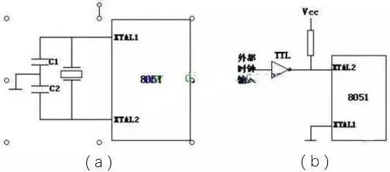
Clock Circuit:(a) Internal clock circuit, (b) External clock circuit
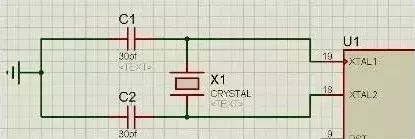
In the internal clock circuit, a quartz crystal oscillator and two trimmer capacitors must be connected across the XTAL1 and XTAL2 pins to form the oscillation circuit, typically with C1 and C2 values of 30pF. The frequency of the crystal oscillator is typically between 1.2MHz and 12MHz.For the external clock circuit, XTAL1 must be grounded, and the XTAL2 pin connects to the external clock. There are no special requirements for the external clock signal, as long as a certain pulse width is guaranteed, and the clock frequency is below 12MHz.
The oscillation signal from the crystal oscillator is sent from the XTAL2 pin to the internal clock circuit, which divides this oscillation signal by two, generating two-phase clock signals P1 and P2 for the microcontroller to use.The period of the clock signal is called the state time S, which is twice the oscillation period. The P1 signal is valid during the first half of each state, while the P2 signal is valid during the second half of each state.The CPU coordinates the effective operation of various parts of the microcontroller using the two-phase clock signals P1 and P2 as the basic timing.
02
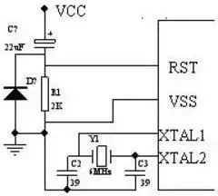
The MCS-51 has a high-gain inverting amplifier, with its input (XTAL1) and output (XTAL2) used for connecting an external quartz crystal and trimmer capacitors to form the oscillator, as shown in the figure.The capacitors C2 and C3 have a fine-tuning effect on the frequency, and the typical range for their capacity is 30pF ± 10pF.The oscillation frequency is typically between 1.2 and 12MHz.
When using an external clock, the XTAL2 of the 8051 is used to input the external clock signal, while XTAL1 is grounded.
03
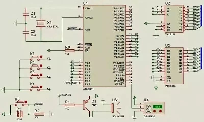
The above figure is the schematic diagram of the clock circuit.It consists of the minimum microcontroller system, microcontroller reset circuit, key circuit, digital tube position selection circuit, digital tube segment selection circuit, digital tube display circuit, buzzer circuit, and temperature acquisition circuit.
The microcontroller’s P2 port is used for digital-to-analog output, while P1^4, P1^5, and P1^6 are connected to the 74HC138 for digital tube position selection. The key circuit connects to P1^0, P1^1, P1^2, and P1^3, and through program control, scans the signals of these four pins to adjust the time.The buzzer is connected to a transistor 8550, ultimately connecting to P1^7, and time setting activates it to sound.The temperature sensor connects to P3^7, converting the collected analog signal into a digital signal to send to the microcontroller.
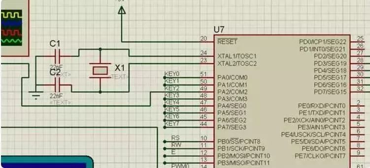
04 Clock circuit and output I/O circuit of the ATmega16 microcontroller:
05 Key processing is set as follows:When no key is pressed, the clock runs normally;When K1 is pressed once, the clock stops; pressing K2 adjusts the seconds;When K1 is pressed twice, pressing K2 adjusts the minutes;When K1 is pressed three times, pressing K2 adjusts the hours; when K1 is pressed four times, the time setting is complete, and the clock runs normally according to the set time.
Pressing K3 once enters the alarm clock setting interface, and the clock continues to run; pressing K2 sets the seconds;When K3 is pressed twice, pressing K2 sets the minutes;When K3 is pressed three times, pressing K2 sets the seconds;When K3 is pressed four times, the alarm clock setting is complete, entering the clock display interface.The circuit diagram is as follows:
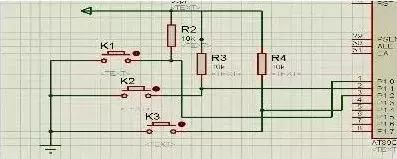
Independent key circuit
06 The microcontroller uses an external 12MHz crystal oscillator to form an oscillation circuit as the clock source. The principle of the clock circuit is shown in the figure below.
07
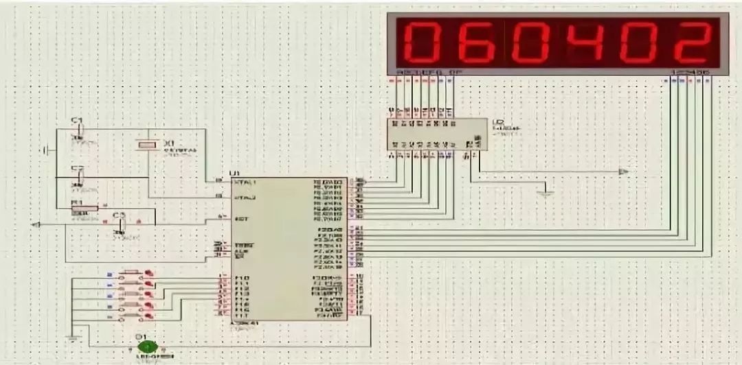
P10 controls which digit of hours, minutes, and seconds to adjust, P11 adjusts the increment of hours, minutes, and seconds, P12 shows the time when pressed, P13 shows the alarm when pressed, and P14 shows the stopwatch, with P14 also serving as the pause and reset switch for the stopwatch.


To help everyone learn better, Changxue Electronics has specially added a public account focused on microcontrollers and EDA, pushing relevant knowledge daily, hoping to assist your learning!