The following content is a collection of knowledge and techniques I have gained from recently soldering surface mount components, which I am now selflessly sharing with you (if you can understand it, then great! ~ (~ ̄▽ ̄)~). However, I want you to know that soldering is not something you can learn in just a few tries; it requires practice to master.
Do I really know how to solder surface mount components?
Recently, our company launched a new product, and I have been helping to solder the boards, which made me realize that my soldering skills need improvement. I always thought my soldering technique was “not bad,” but it turns out that being able to solder a few through-hole components does not mean I am skilled; any electronics major could easily do that without any pressure.
Soldering surface mount components on a PCB is where true skill is tested, as you encounter densely packed chip pins and capacitors and resistors smaller than grains of sand. Issues like cold joints and short circuits frequently occur and are very hard to detect, requiring a high level of technique and patience. More importantly, there are some small tips and details to pay attention to, some of which I had previously overlooked.
Soldering is second nature for experienced hardware engineers, but I am just an average beginner, so I appreciate your guidance and hope you won’t laugh at me.
About the Soldering Iron
A temperature-adjustable soldering station seems essential; otherwise, how do you know the temperature of your soldering iron? Haha~~~ With a soldering station, a chisel tip soldering iron becomes standard equipment (I find it quite troublesome to solder surface mount components with a pointed tip iron), along with solder, sponges, and flux, forming a complete soldering family.
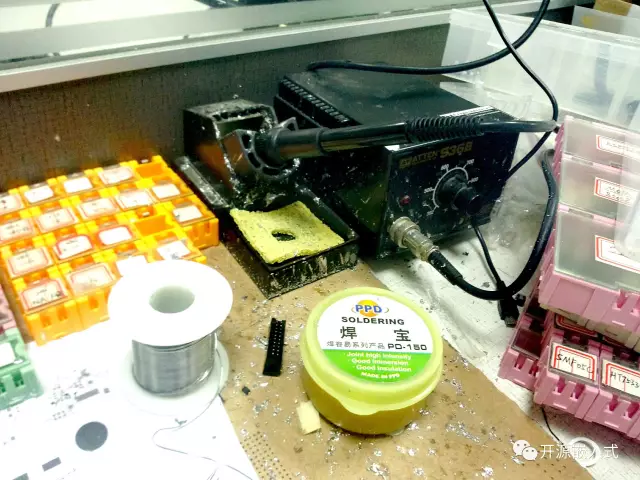
When using the soldering iron, pay attention to the following points:
-
The soldering iron tip is easily damaged; always keep it tinned.
-
Avoid striking the soldering iron tip against hard objects to prevent deformation.
-
Set the temperature to around 350°C when soldering surface mount components.
-
Avoid leaving the soldering iron heated for too long; otherwise, it can burn out (lower the temperature when not in use for a long time).
-
Do not soak the sponge too much; wring it out to keep it soft.
-
Do not touch strange objects with the soldering iron; otherwise, it will emit strange smells →_→.
Indicating Values for Surface Mount Resistors and Capacitors
Let’s briefly talk about the markings on surface mount components; if you can’t understand the value markings for resistors and capacitors, you won’t even be able to find the components!!!
Direct Marking Method
Direct marking method: The resistance value is marked on the surface of the surface mount resistor using numbers and unit symbols, with the permissible error directly expressed as a percentage. If there is no deviation marked on the surface mount resistor, it is generally ±20%. In the direct marking method, unit symbols can replace decimal points for clarity, but it is only suitable for larger components and is not universally applicable internationally.
This means directly writing out the value and unit, such as the commonly mentioned 100Ω, 4K7 (4.7K), 220uF, etc.
Digital Method
Digital method: A three-digit numerical representation is used to indicate the nominal value on the surface mount resistor. The digits from left to right represent the significant digits, with the last digit indicating the number of zeros. The deviation is usually indicated with a letter symbol.
For example, a resistance of 103 means 10 followed by three zeros, which equals 10000, or 10K ohms. Similarly, a resistance of 331 equals 330 ohms. For capacitors, the unit is pF; for example, a capacitor marked 104 equals 100000pF = 100nF = 0.1uF.
It is particularly important to note the unit conversions for capacitors: pF is the smallest, followed by nF, then uF, and finally F. 1F = 10^6uF = 10^9nF = 10^12pF.
Next, I will explain some precautions for soldering different components I have encountered recently.
Chips
QFP Package
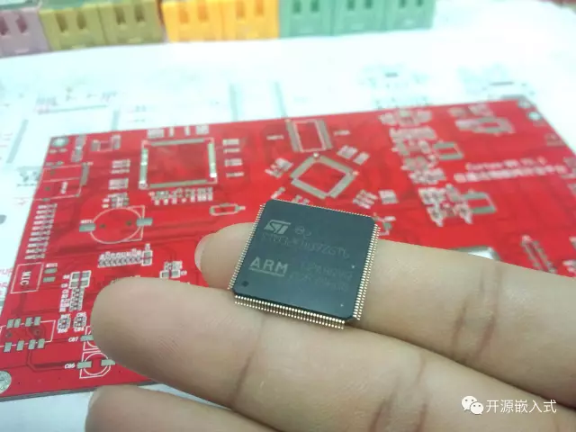
For SOP packaged chips with a larger pin pitch than QFP, you can generally just apply solder with a chisel tip and scrape it off a couple of times to finish, which is not a big deal. Here, I will focus on the soldering of densely packed QFP packages. First, secure the chip, and here are the steps:
-
Place the chip flat on the PCB; do not apply solder to the pads, or the chip will not lie flat, leading to cold solder joints.
-
Ensure the direction of pin one of the chip corresponds with the PCB (pin one is usually located at the small circle or the lower left corner of the silkscreen).
-
Align the chip’s pins with the pads; aligning all four sides is a very challenging task.
-
Fix the edge pins on one side with solder, check the alignment on all four sides; if misaligned, there is still a chance to adjust the chip’s position with the soldering iron.
-
Fix the pins on the opposite side with solder.
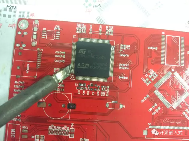
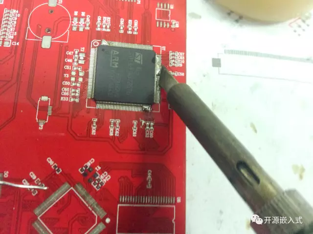
Once the chip is secured, you can start soldering (many components follow the “fix first, then solder” routine). When soldering, keep the following in mind:
-
Choose a side that has not been soldered and start soldering.
-
Dip the soldering iron in flux and apply it to the pins and pads on one side.
-
Add solder from one side until it forms a solder ball.
-
Use the soldering iron to draw the solder to the other side; the pins that have been wetted with solder will naturally solder themselves.
-
Remove excess solder using the stickiness of the soldering iron tip.
-
Repeat the process for the remaining three sides.
-
After soldering all four sides, check for any pin connections or short circuits, and re-solder if necessary.
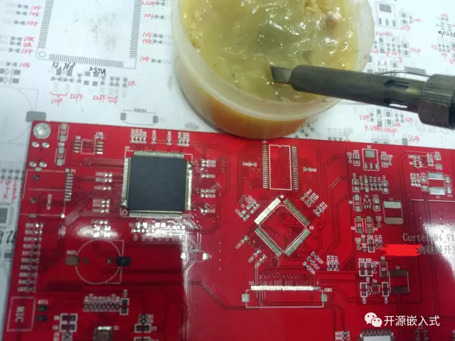
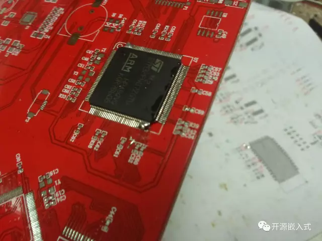
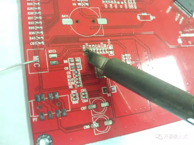
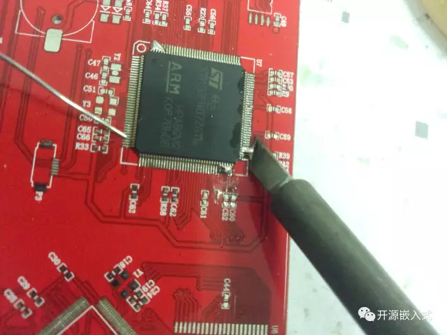
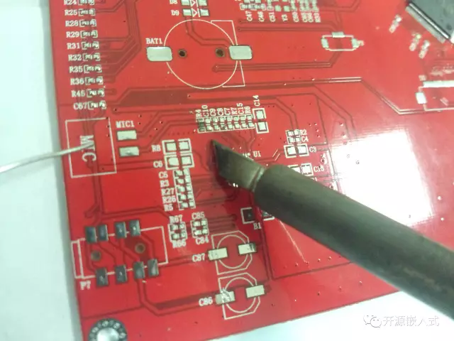
In summary, when soldering chips, remember two key points: 1. Add more solder at first; it’s okay if the pins are connected; separate them slowly after soldering. 2. Use plenty of flux, as flux improves the flow of solder, preventing it from becoming a sticky lump.
There’s a video on YouTube that specifically teaches soldering QFP chips: Professional SMT Soldering: Hand Soldering Techniques – Surface Mount.
QFN Package
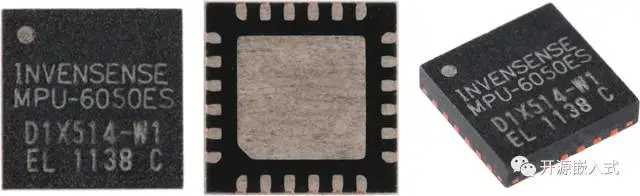
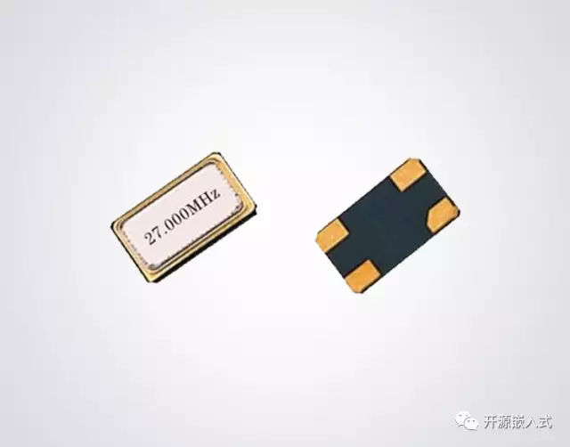
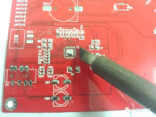
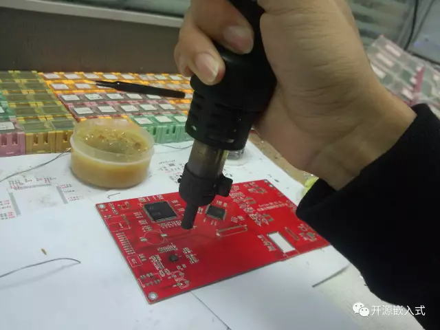
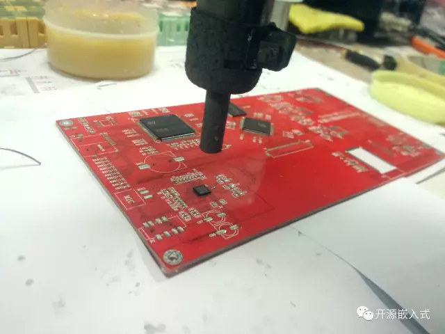
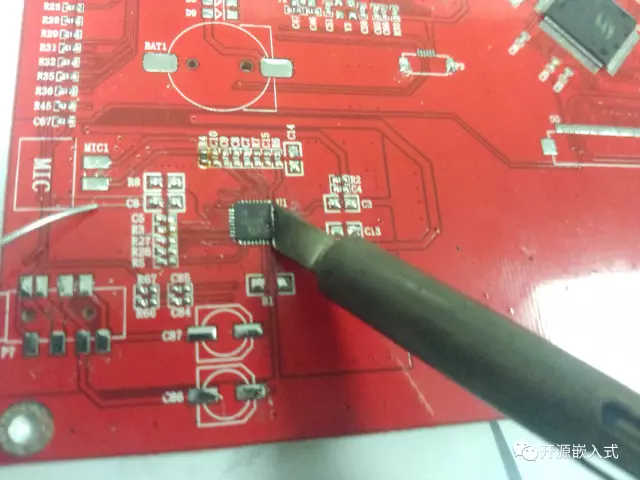
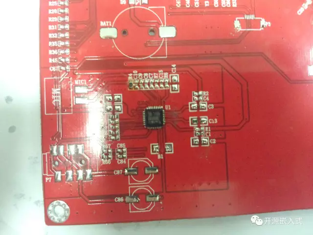
For QFN chips, which do not have exposed pins (like the ESP8266), or for 4-pin surface mount crystals with contact points on the bottom, soldering directly with a soldering iron is quite difficult and unreliable. The correct method should be to use a hot air gun (I was so excited the first time I used a hot air gun! ~ (~ ̄▽ ̄)~), but how do you use it?
-
Apply a thin layer of solder on all pad surfaces and the large pad in the middle.
-
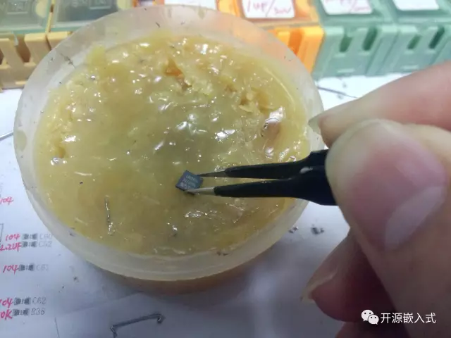
Use tweezers to hold the chip and apply some flux to the bottom surface.
-
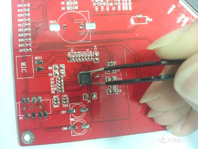
Place the chip on the pad, roughly aligning its position.
-
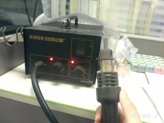
Set the hot air gun temperature to around 350°C and the airflow to the minimum.
-
Hold the hot air gun vertically above the PCB at a height of about 8CM, first heat the area around the chip, and finally aim the gun at the chip.
-
The flux and solder will melt, and due to liquid tension, the chip will automatically adhere to the correct position.
-
Turn off the hot air gun and check the chip’s connections carefully; be cautious as the PCB can get hot.
-
If necessary, use a soldering iron to re-solder around the edges.
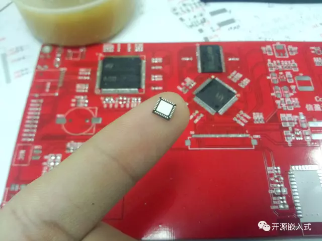
Important notes:
-
The airflow should not be too strong, and the height should be appropriate; otherwise, it can blow away the chip or surrounding small capacitors and resistors.
-
If the chip does not automatically adhere, you can use tweezers to assist in adjusting it or press it down slightly.
-
Be careful not to add too much solder to the central pad, or the chip will push the solder outwards, causing pin short circuits.
-
The hot air gun is really very hot!
Capacitors, Resistors, and Diodes
Capacitors and resistors are the most common components, and the typical soldering method is: first tin one pad, use tweezers to fix one side, and then solder the other side. The biggest advantage of this method is that it is easy to adjust the component position (because of the assistance of tweezers), resulting in neatly soldered components. However, the downside is obvious—efficiency is too low (also due to needing tweezers). Especially when dealing with a PCB with many components, soldering each pin one by one seems a bit slow…
Now I use a quick soldering method called “soldering iron sticky component,” sacrificing the aesthetic arrangement of components for higher efficiency. This method was taught to me by the company’s expert engineer, allowing me to solder both pins of a component simultaneously without tweezers, effectively doubling the efficiency. The steps are as follows:
-
Tin both pads.
-
Remove excess solder from the soldering iron, keeping a thin layer of solder covering the tip (the soldering iron needs solder to have stickiness).
-
Lay the component flat, and touch the side of the component with the soldering iron tip to stick it horizontally.
-
Position the soldering iron with the component above the pads, heating both ends and slightly adjusting the component position with the soldering iron tip.
-
Remove the soldering iron in the direction of the component.
-
Solder adjacent components from left to right.
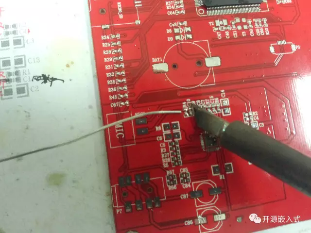
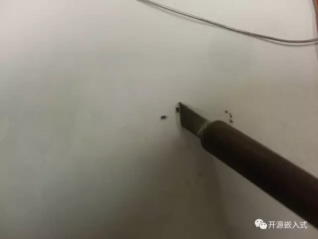
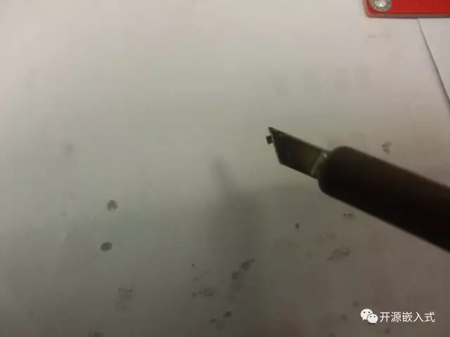
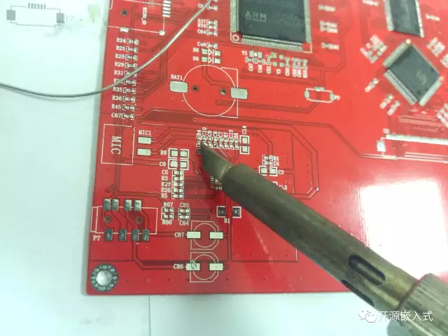
The key step in using the soldering iron to “stick” components is to slowly approach the component’s side with the soldering iron and gently touch it. Note that the soldering iron tip must have solder to be sticky, but not too much solder; otherwise, the liquid tension will make the component hard to control. How do you cover the soldering iron tip with a thin layer of solder? First, add solder, then shake it a few times in the direction of the iron (imagine the hand motion of throwing a dart); in actual soldering, sponges are rarely used; excess solder is usually just shaken off, so this “shaking” action is very important (sponges can clean the solder too much, which is not good; only use them when there is dirt; shaking it off will leave a nice thin layer of solder naturally).
Using tweezers can easily lead to cold joints, while using solder to support the components can greatly reduce the probability of cold joints.
When using this soldering method, you shouldn’t just pursue speed; while aiming for efficiency, ensure quality as well, trying to solder the components neatly. Never, ever create cold joints. Additionally, control the amount of solder; if both ends form a ball shape, that is already too much; the ideal state should look like this (according to IPC standards):
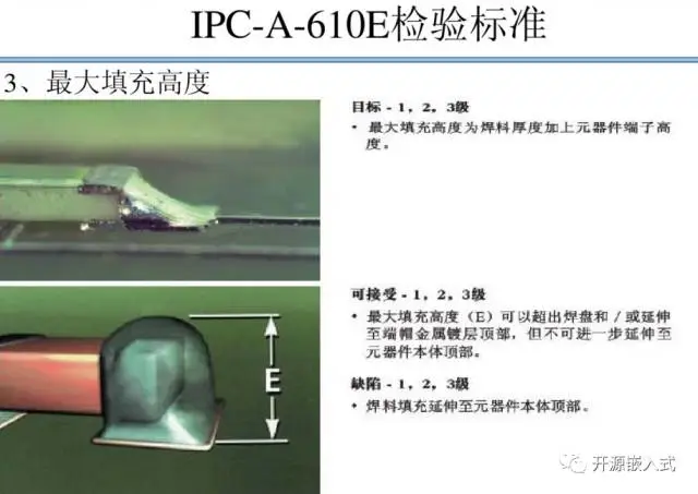
For larger surface mount electrolytic capacitors and diodes, do not heat both ends with the soldering iron simultaneously, and be cautious not to add too much solder to the pads; otherwise, you may end up with the awkward situation of the component being taller on one side than the other.
Socket Components
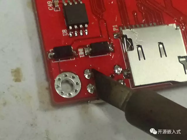
For sockets like USB, SD cards, SIM cards, etc., you must solder the pins first, then solder the fixing pins, because if you fix the socket first and the position is incorrect, you won’t be able to adjust it; be careful not to solder it crooked. For sockets with fixed holes, like Micro-USB, after soldering the pins, flip the board over and add solder to the back of the fixing holes, allowing the solder to flow to the component side for fixing. The reason is that some Micro-USB sockets are not fully enclosed, and when soldering the fixing pins next to the components, it is easy to get solder into the socket, preventing the plug from fitting in (in short, solder the holes on the back side).
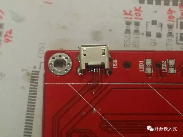
There is a particularly tricky type of flat cable socket called the “FPC socket,” which has very dense pins and serious soldering issues, requiring a lot of rosin to manage; the usual sticky flux does not work well, and I have damaged quite a few.
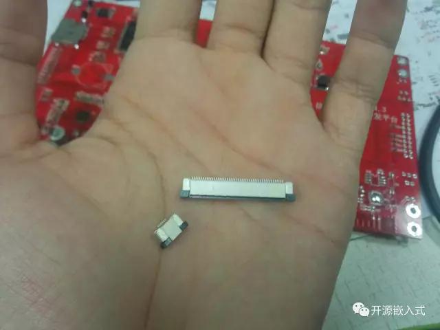
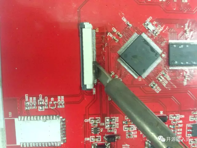
Finally, it is important to note that socket components need to be soldered securely since they are frequently plugged and unplugged. When soldering the fixing pins, you can raise the soldering iron temperature slightly and solder for a longer time. Larger components (or those with a larger contact surface) also require extended heating time and higher temperatures to ensure a solid connection.
Order of Soldering
To solder a board more efficiently and reliably, you must follow certain principles (like “small to large”) and not solder randomly based on which components look good. Generally, my process when I receive a board is as follows:
-
Print the PCB package diagram (the pattern printed on the board) and mark the sizes and chip models of each component with a red pen based on the circuit schematic (this step can be skipped for small boards with few components).
-
Solder the power section, including various voltage regulators and conversion circuits, and check the voltage at various points with a multimeter after soldering (this step can be skipped for small boards).
-
Solder the main chips (MCU, Flash chips, device driver chips, etc.).
-
Solder smaller components like capacitors, resistors, and diodes.
-
Solder larger components like capacitors and diodes.
-
Solder peripheral components like switches, sockets, and antennas.
-
Power on and test.
-
Clean the PCB with cleaning fluid and a lint-free cloth.
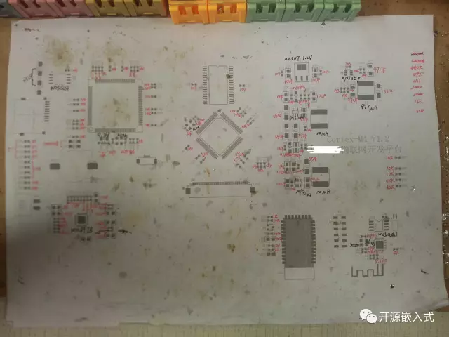
PS: For more complex PCBs, you should solder the power circuit first, test the voltage values at various points, and then solder the digital circuit section, working in modules while testing to promptly eliminate issues and ensure correct connections.
Of course, it is not mandatory to follow this exact order; you should explore and find the most suitable order based on the differences in components and PCBs.
Common Soldering Issues
Uneven Solder Joints
Beginners often face the issue of uneven solder joints, which are not only unattractive but can also lead to cold joints and sharp points. The main reasons for uneven solder joints are that the soldering iron temperature is insufficient to fully melt the solder, which can be resolved by increasing the soldering iron temperature. The second reason is that the soldering time is too long, causing the flux to evaporate completely, leading to dull and unflowing solder; the solution is to add solder first, then remove the excess solder with the soldering iron.
Pin Shorting
When soldering components with densely packed pins, such as chips, it is common for two or more pins to get soldered together, making them difficult to separate. This occurs due to excessive soldering time, which causes the flux in the solder to evaporate, leading to a loss of fluidity. Most solder wires contain flux; in this case, you can add more solder and quickly remove the excess. A more direct method is to add rosin or other flux to make the solder more fluid.
Clearing Blocked Holes
Having solder block the holes of through-hole components can be quite frustrating. If you find that a solder sucker does not work or drilling does not clear the hole, there is a simpler method—tap! Utilize the fluidity and tension of the liquid, along with Newton’s first law (inertia), to perfectly resolve the issue. Here’s how:
-
Add solder to the side of the pad where the hole is blocked (yes, add more when it’s blocked!).
-
Continue heating the blob of solder blocking the hole with the soldering iron.
-
Hold the board with your left hand while keeping the soldering iron heated with your right hand.
-
Simultaneously lift and move your hands, raising the board.
-
Quickly strike the edge of the board against the edge of the table while stopping the soldering iron just before the board hits the table.
-
The molten solder will be “flung out” of the hole due to the impact.
Be careful not to be too forceful; otherwise, you may damage the board. Remember, there is no solder hole that cannot be cleared with a tap; if there is, just add more solder and tap a few more times. PS: This trick does not work well with oversized PCBs.
This method can also be applied to desoldering components. In the past, I would use a solder sucker to remove one pin at a time. Now, I can simply add a large blob of solder to heat them all at once, then quickly remove the component while it’s hot, and clear the holes afterward, making the process convenient and efficient.
There’s also a video on YouTube that specifically teaches desoldering techniques: Desoldering Techniques.
Some Minor Details
-
Ensure the component size matches the pad size; do not solder 0805 components onto 0603 pads.
-
To prevent solder from sticking to unnecessary areas on the PCB (such as the company logo), you can cover those areas with masking tape before soldering.
-
Keep a pile of commonly used components in a fixed position so you don’t have to dig through the component box each time.
-
When taking small SMD components from the component box, pressing down with the tip of your right pinky can pick up several at once, which is much faster than using tweezers.
-
If I think of anything else, I will add it later…
In Conclusion
Finally, I want to thank the engineers for trusting me with the product sample to solder; it seems that only under strict requirements can one discover their shortcomings and improve (so everyone should practice in real situations instead of just playing around). Although I have encountered many new components, there is still a colorful electronic world waiting for me to discover.
Disclaimer: This article is copyrighted by the original author and does not represent the views of the association. The articles pushed by the “Jiangxi Province Electronic Circuit Industry Association” are for sharing purposes only and do not represent the position of this account. If there are any copyright issues, please contact us for deletion.