Follow and star the public account “Embedded Development Notes”,so you won’t miss any exciting content! Previous articles recommended:STM32CUBEMX Tutorial 4 — UART (USART) Configuration and Redirecting printf OutputSTM32CUBEMX Tutorial 3 — Using External Interrupts (EXTI)STM32CUBEMX Tutorial 2 — Using GPIO, Input/OutputSTM32CUBEMX Tutorial 1 — Environment Setup and New Project CreationDetailed Installation Guide for STM32CUBEMX1. Introduction to DMADMA (Direct Memory Access) is a very useful peripheral in STM32 for direct memory access (or data transfer).DMA transfers data without CPU involvement in controlling the transfer, nor does it require interrupt handling for data transfer, purely using hardware to create a direct path for data transfer between RAM and I/O devices, greatly improving CPU efficiency.Since I am using the STM32F103ZET6, I will explain based on this model. There are some differences among different specifications of the same model, please refer to the user manual for specifics.The STM32F103ZET6 has two DMA controllers, DMA1 and DMA2, where DMA1 has 7 channels and DMA2 has 5 channels. Different DMA controllers map to different peripheral requests. The mapping table is as follows: The block diagram of the DMA controller is as follows:
 From the above diagram, we can see:(1) DMA Data Transfer RequestFor a peripheral to transfer data via DMA, it must first send a DMA request to the DMA controller. After receiving the request signal, the DMA controller will send a response signal to the peripheral. Once the peripheral responds and the DMA controller receives the response signal, the DMA transfer will start until it is completed.(2) DMA Channel MappingDMA1 has 7 channels, and DMA2 has 5 channels, with each channel corresponding to different peripheral DMA requests.Although each channel can receive requests from multiple peripherals, it can only accept one request at a time and cannot handle multiple requests simultaneously.(3) Multi-Request Arbitration MechanismWhen multiple DMA channels request a transfer, the arbiter manages the order of responses.The arbiter manages DMA channel requests in two phases: the first phase is the software phase, which can be set in the DMA_CCRx register, with 4 levels: very high, high, medium, and low priority.The second phase is the hardware phase. If two or more DMA channel requests have the same priority, their priority is determined by the channel number, with lower numbers having higher priority, for example, channel 0 has higher priority than channel 1.This article demonstrates using DMA1 and USART1 to transfer data from a memory buffer (Data_buffer) to USART1 output.From the above, we know that USART1_TX is mapped to DMA1 channel 4.2. Configuring DMA in STM32CUBEMX(1) Open the USART configuration project from the last issue and enable the DMA function.Refer to my previous article for USART configuration:STM32CUBEMX Tutorial 4 — UART (USART) Configuration and Redirecting printf OutputSelect USART1’s TX and add DMA, as shown below:
 (2) Add DMA channel mapping to USART1_TX, as shown below:
 (3) The DMA channel mapping direction is Memory –> Peripheral, with the other settings as follows:
 Explanation:Direction: Transfer direction. There are two types: Memory to Peripheral: from memory to peripheral;Peripheral to Memory: from peripheral to memory;Mode: There are two modes:Normal: In normal mode, after DMA initialization is complete, it transfers once, and to transfer again, DMA must be re-initialized.Circular: In circular mode, after DMA initialization is complete, it will keep transferring.DMA Data Width:Byte: byteHalf Word: half wordWord: wordAfter code generation, the DMA initialization code is as follows:
void MX_DMA_Init(void){ /* DMA controller clock enable */ __HAL_RCC_DMA1_CLK_ENABLE(); /* DMA interrupt init */ /* DMA1_Channel4_IRQn interrupt configuration */ HAL_NVIC_SetPriority(DMA1_Channel4_IRQn, 0, 0); HAL_NVIC_EnableIRQ(DMA1_Channel4_IRQn);}
After code generation, the DMA initialization code is as follows:
/* USART1 DMA Init */ /* USART1_TX Init */ hdma_usart1_tx.Instance = DMA1_Channel4; hdma_usart1_tx.Init.Direction = DMA_MEMORY_TO_PERIPH; hdma_usart1_tx.Init.PeriphInc = DMA_PINC_DISABLE; hdma_usart1_tx.Init.MemInc = DMA_MINC_ENABLE; hdma_usart1_tx.Init.PeriphDataAlignment = DMA_PDATAALIGN_BYTE; hdma_usart1_tx.Init.MemDataAlignment = DMA_MDATAALIGN_BYTE; hdma_usart1_tx.Init.Mode = DMA_NORMAL; hdma_usart1_tx.Init.Priority = DMA_PRIORITY_LOW; if (HAL_DMA_Init(&hdma_usart1_tx) != HAL_OK) { Error_Handler(); } __HAL_LINKDMA(uartHandle,hdmatx,hdma_usart1_tx);Since this article configures the transfer of data from memory to USART via DMA, we need to define the area for sending data. As follows:
/* Private user code ---------------------------------------------------------*//* USER CODE BEGIN 0 */uint8_t Tx_data[] = {"DMA Test, WeChat public account: Embedded Development Notes!\r\n"};/* USER CODE END 0 */Call the API interface to send data:
HAL_UART_Transmit_DMA(&huart1, (uint8_t*)Tx_data, sizeof(Tx_data));The experimental phenomenon is as follows: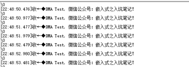
If you find this article helpful, please follow us!
Please give us a recommendation!