
Hello everyone, I am Pi Zi Heng, a serious technical person. Today, I will share with you the design and implementation of an automatic baud rate recognition program for UART in embedded systems.
The UART (Universal Asynchronous Receiver-Transmitter) is the most basic, commonly used, and simplest communication (data transmission) method in embedded systems. It can be said to be the introductory teacher for engineers entering the field of communication. At the same time, UART printing is also a classic debugging and interaction method in embedded projects.
The simplest UART uses only two unidirectional signal lines: TXD (transmit data) and RXD (receive data). These two signal lines work independently, allowing for separate or simultaneous data transmission and reception, which is known as full-duplex communication. UART does not have a master-slave concept and does not require a dedicated clock signal (SCK), so UART communication is considered asynchronous transmission.
Speaking of asynchronous transmission, we must mention the issue of baud rate (the number of bits transmitted per second). Both communicating parties must use the same baud rate to complete correct data transmission. Normally, we pre-agree on the baud rate for two UART devices, for example, when an MCU communicates with a host computer, the MCU program initializes the UART peripheral at a baud rate of 115200, and the host computer’s serial debugging assistant is also set to 115200 baud rate, allowing both sides to work together.
Sometimes, we also hope to have a flexible way to agree on the baud rate, such as setting a baud rate arbitrarily in the host computer’s serial debugging assistant before establishing communication, then sending data at this baud rate, and the MCU can automatically recognize this baud rate and initialize the UART peripheral with the recognized baud rate before proceeding with subsequent data transmission. This method is called automatic baud rate recognition. Today, I will share the program design for implementing automatic baud rate recognition in the MCU:
- Program homepage: https://github.com/JayHeng/cortex-m-apps/tree/master/components/autobaud
1. Automatic Baud Rate Recognition Program Design for UART
1.1 Function Interface Definition
First, we design the header file for the automatic baud rate recognition program: autobaud.h, which directly defines the following three interface function prototypes. It covers the necessary initialization process init(), deinit(), and the core baud rate recognition function get_rate().
//! @brief Initialize baud rate recognition
void autobaud_init(void);

//! @brief Check if baud rate recognition is complete and get the baud rate value
bool autobaud_get_rate(uint32_t *rate);

//! @brief Disable baud rate recognition
void autobaud_deinit(void);
1.2 Recognition Design Concept
Regarding recognition, since the data from the host computer comes from the RXD pin, the MCU needs to configure the RXD pin as a normal digital input GPIO (this pin needs to be pulled up, keeping a high level by default) and then detect the level transition of this GPIO (usually using the falling edge) and time it.
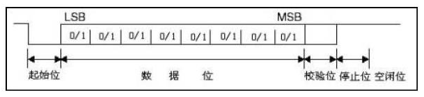
The following diagram shows the typical timing of a single-byte UART transmission. The I/O idle state is high, and transmission always starts with a 1-bit low-level start bit, followed by 8 bits of data from LSB to MSB, an optional parity bit (which we will not enable for now), and finally ends with a 1-bit high-level stop bit, returning the I/O to a high-level idle state.
- Note 1: The falling edge transition is detected because the I/O idle state is high, and the presence of the start bit ensures that every byte transmission cycle always starts from the falling edge.
- Note 2: The existence of the start and stop bits also provides baud rate tolerance, allowing data transmission to proceed normally with a baud rate error of up to 3% between the two communicating parties.
Although we do not need to agree on the baud rate of the host computer, to achieve automatic baud rate recognition, the initial data transmitted from the host computer must be pre-agreed upon (which can be understood as a secret handshake). This involves counting the number of level transitions detected by the MCU and the corresponding timing calculations. After the MCU completes recognition, it sends the secret handshake back to the host computer for confirmation.
The secret handshake designed by me consists of two bytes: 0x5A and 0xA6. The two-byte handshake has better fault tolerance compared to a single-byte handshake (to prevent interference on the I/O line that could lead to misrecognition). Based on the specified handshake and the UART transmission timing diagram, we can easily derive the following constant definitions:
enum _autobaud_counts
{
    //! Number of falling edges corresponding to the 0x5A byte
    kFirstByteRequiredFallingEdges = 4,
    //! Number of falling edges corresponding to the 0xA6 byte
    kSecondByteRequiredFallingEdges = 3,
    //! Actual number of bits from the first falling edge to the last falling edge for the 0x5A byte (from start bit to stop bit)
    kNumberOfBitsForFirstByteMeasured = 8,
    //! Actual number of bits from the first falling edge to the last falling edge for the 0xA6 byte (from start bit to stop bit)
    kNumberOfBitsForSecondByteMeasured = 7,
    //! Maximum allowed timeout (us) between two falling edges
    kMaximumTimeBetweenFallingEdges = 80000,
    //! Align the actual detected baud rate value for better configuration of the UART module
    kAutobaudStepSize = 1200
};
In the above constant definitions, kMaximumTimeBetweenFallingEdges specifies the maximum allowed time interval between two falling edges. If this time is exceeded, the automatic baud rate program will discard the previously counted falling edges and start recognition from the beginning. This design is also to prevent level interference on the I/O line that could lead to misrecognition.
The kAutobaudStepSize constant is used to align the detected baud rate value. The formula is rounded = stepSize * (value/stepSize + 0.5), where value is the actual detected baud rate value, and rounded is the aligned baud rate value. Using the aligned baud rate value can better configure the UART peripheral (this is related to the design of the baud rate generator SBR in the UART module).
Finally, we need to design the I/O level falling edge detection method. This can be done using software polling (by continuously reading the I/O input level and comparing the current value with the previous value) or using the edge interrupt function provided by the GPIO module. The latter is recommended because it provides more accurate timing and does not block the system. When a falling edge is detected, the following pin_transition_callback() function is called to count the transitions and time them.
//! @brief Callback function for pin falling edge transition
static void pin_transition_callback(void);
1.3 Main Code Implementation
Based on the design concepts described in the previous section, we can easily write the following main code (autobaud_irq.c), where I have provided detailed comments. One point to note is regarding the system timing, which can refer to my previous article “Design and Implementation of a General Microsecond Timing Function Framework in Embedded Systems”.
//! @brief Enable GPIO pin interrupt
extern void enable_autobaud_pin_irq(pin_irq_callback_t func);
//! @brief Disable GPIO pin interrupt
extern void disable_autobaud_pin_irq(void);

//!< Number of detected falling edges
static uint32_t s_transitionCount;
//!< Count value during the detection of the 0x5A byte
static uint64_t s_firstByteTotalTicks;
//!< Count value during the detection of the 0xA6 byte
static uint64_t s_secondByteTotalTicks;
//!< System count value at the last falling edge occurrence
static uint64_t s_lastToggleTicks;
//!< Maximum timeout count value between falling edges
static uint64_t s_ticksBetweenFailure;

void autobaud_init(void)
{
    s_transitionCount = 0;
    s_firstByteTotalTicks = 0;
    s_secondByteTotalTicks = 0;
    s_lastToggleTicks = 0;
    // Calculate the maximum timeout count value between falling edges
    s_ticksBetweenFailure = microseconds_convert_to_ticks(kMaximumTimeBetweenFallingEdges);
    // Enable GPIO pin interrupt and register the interrupt handling callback function
    enable_autobaud_pin_irq(pin_transition_callback);
}

void autobaud_deinit(void)
{
    // Disable GPIO pin interrupt
    disable_autobaud_pin_irq();
}

bool autobaud_get_rate(uint32_t *rate)
{
    if (s_transitionCount == (kFirstByteRequiredFallingEdges + kSecondByteRequiredFallingEdges))
    {
        // Calculate the actual detected baud rate value
        uint32_t calculatedBaud =
            (microseconds_get_clock() * (kNumberOfBitsForFirstByteMeasured + kNumberOfBitsForSecondByteMeasured)) /
            (uint32_t)(s_firstByteTotalTicks + s_secondByteTotalTicks);

        // Align the actual detected baud rate value
        // Formula: rounded = stepSize * (value/stepSize + .5)
        *rate = ((((calculatedBaud * 10) / kAutobaudStepSize) + 5) / 10) * kAutobaudStepSize;

        return true;
    }
    else
    {
        return false;
    }
}

void pin_transition_callback(void)
{
    // Get the current system count value
    uint64_t ticks = microseconds_get_ticks();
    // Count the detected falling edge
    s_transitionCount++;

    // If the interval between this falling edge and the last falling edge is too long, restart detection
    uint64_t delta = ticks - s_lastToggleTicks;
    if (delta > s_ticksBetweenFailure)
    {
        s_transitionCount = 1;
    }

    switch (s_transitionCount)
    {
        case 1:
            // Start time for detecting the 0x5A byte
            s_firstByteTotalTicks = ticks;
            break;

        case kFirstByteRequiredFallingEdges:
            // Get the count value during the detection of the 0x5A byte
            s_firstByteTotalTicks = ticks - s_firstByteTotalTicks;
            break;

        case (kFirstByteRequiredFallingEdges + 1):
            // Start time for detecting the 0xA6 byte
            s_secondByteTotalTicks = ticks;
            break;

        case (kFirstByteRequiredFallingEdges + kSecondByteRequiredFallingEdges):
            // Get the count value during the detection of the 0xA6 byte
            s_secondByteTotalTicks = ticks - s_secondByteTotalTicks;
            // Disable GPIO pin interrupt
            disable_autobaud_pin_irq();
            break;
    }

    // Record the system count value at the occurrence of this falling edge
    s_lastToggleTicks = ticks;
}
2. Implementation of Automatic Baud Rate Recognition Program for UART
The previous discussion was hardware-independent design, but it ultimately needs to be implemented on a specific MCU platform, where the GPIO interrupt part is closely related to the MCU. We will take the NXP i.MXRT1011 as an example to introduce the hardware implementation.
2.1 Implementation Using Pin Interrupt (Based on i.MXRT1011)
The NXP MIMXRT1010-EVK has an onboard debugger DAPLink, which also integrates USB to UART functionality. The corresponding UART pins are IOMUXC_GPIO_09_LPUART1_RXD and IOMUXC_GPIO_10_LPUART1_TXD. We will use GPIO1[9] for automatic baud rate detection, and the implementation code is as follows:
typedef void (*pin_irq_callback_t)(void);
static pin_irq_callback_t s_pin_irq_func;

//! @brief UART pin function switching function
void uart_pinmux_config(bool setGpio)
{
    if (setGpio)
    {
        IOMUXC_SetUartAutoBaudPinMode(IOMUXC_GPIO_09_GPIOMUX_IO09, GPIO1, 9);
    }
    else
    {
        IOMUXC_SetUartPinMode(IOMUXC_GPIO_09_LPUART1_RXD);
        IOMUXC_SetUartPinMode(IOMUXC_GPIO_10_LPUART1_TXD);
    }
}

//! @brief Enable GPIO pin interrupt
void enable_autobaud_pin_irq(pin_irq_callback_t func)
{
    s_pin_irq_func = func;
    // Enable falling edge interrupt for GPIO1_9
    GPIO_SetPinInterruptConfig(GPIO1, 9, kGPIO_IntFallingEdge);
    GPIO1->IMR |= (1U << 9);
    NVIC_SetPriority(GPIO1_Combined_0_15_IRQn, 1);
    NVIC_EnableIRQ(GPIO1_Combined_0_15_IRQn);
}

//! @brief GPIO interrupt handling function
void GPIO1_Combined_0_15_IRQHandler(void)
{
    uint32_t interrupt_flag = (1U << 9);
    // Only when the GPIO1_9 interrupt occurs
    if ((GPIO_GetPinsInterruptFlags(GPIO1) & interrupt_flag) && s_pin_irq_func)
    {
        // Execute the callback function once
        s_pin_irq_func();
        GPIO_ClearPinsInterruptFlags(GPIO1, interrupt_flag);
    }
}
2.2 Testing on MIMXRT1010-EVK
Everything is ready, and we are now going to test it. The main function flow is very simple, and the test results indicate that the expected effect has been achieved. Each time the MCU program is reset and run, the baud rate can be set arbitrarily in the serial debugging assistant.
int main(void)
{
    // Omitted system clock configuration...
    // Initialize timer
    microseconds_init();
    // Configure GPIO1_9 as input GPIO
    bool setGpio = true;
    uart_pinmux_config(setGpio);
    // Initialize baud rate recognition
    autobaud_init();
    // Check if baud rate recognition is complete and get the baud rate value
    uint32_t baudrate;
    while (!autobaud_get_rate(&baudrate));
    // Disable baud rate recognition
    autobaud_deinit();
    // Configure UART1 pins
    setGpio = false;
    uart_pinmux_config(setGpio);
    // Initialize UART1 peripheral
    uint32_t uartClkSrcFreq = BOARD_DebugConsoleSrcFreq();
    DbgConsole_Init(1, baudrate, kSerialPort_Uart, uartClkSrcFreq);

    PRINTF("Autobaud test success\r\n");
    PRINTF("Detected baudrate is %d\r\n", baudrate);

    while (1);
}
Thus, the design and implementation of the automatic baud rate recognition program for UART in embedded systems has been completed. Where is the applause~~~


1. Sign up! Build secure embedded systems — from FreeRTOS to SAFERTOS online course
2. The 6th issue of the 2021 “Microcontroller and Embedded System Applications” electronic journal is freshly out!
3. Huawei’s official notice: HarmonyOS no longer belongs to Huawei!
4. Ingenious use of the MCU’s general-purpose registers that do not reset on SystemReset!
5. With limited resources in microcontrollers, why do so many people want to use RTOS?
6. Remembering the university days obsessed with technology on Children’s Day!

Disclaimer: This article is a network reprint, and the copyright belongs to the original author. If there are any copyright issues, please contact us, and we will confirm the copyright based on the copyright certificate you provide and pay the remuneration or delete the content.