Previous article links:Detailed installation tutorial for STM32CUBEMXSTM32CUBEMX Tutorial 1 — Environment Configuration and New Project CreationWhen learning and using any MCU, the initial step often starts with GPIO. Learning how to configure IO allows you to output the desired voltage levels and read the voltage levels from the IO ports.This article introduces the GPIO of STM32.GPIO (General-Purpose Input/Output) is the abbreviation for general-purpose input/output ports, which serve as the communication channel between the MCU and the external environment.For the Cortex-M3 series MCUs, such as the STM32F103, there are a total of eight modes for GPIO:Input modes:(1) GPIO_Mode_AIN Analog Input(2) GPIO_Mode_IN_FLOATING Floating Input(3) GPIO_Mode_IPD Pull-Down Input(4) GPIO_Mode_IPU Pull-Up InputOutput modes:(1) GPIO_Mode_Out_OD Open-Drain Output(2) GPIO_Mode_Out_PP Push-Pull Output(3) GPIO_Mode_AF_OD Alternate Function Open-Drain Output(4) GPIO_Mode_AF_PP Alternate Function Push-Pull OutputFor detailed descriptions of these modes, it is recommended to refer to the STM32 Chinese reference manual. This article mainly discusses how to use GPIO through CUBEMX to achieve the desired effects.1. GPIO Output ConfigurationThe board I am using has two LEDs, so I will use these two LEDs for demonstration. The schematic connection of the LEDs is as follows: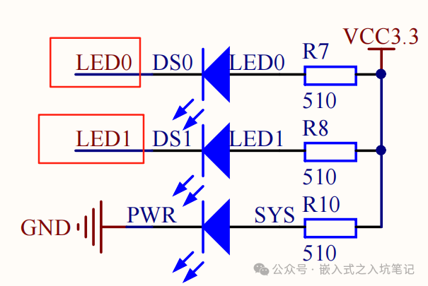 The connection on the MCU is as follows:
 From the diagram, we can see that LED0 is connected to PB5, and LED1 is connected to PE5. The LED lights up when the IO outputs a low level and turns off when it outputs a high level.(1) Create a project and select Pinout & Configuration:
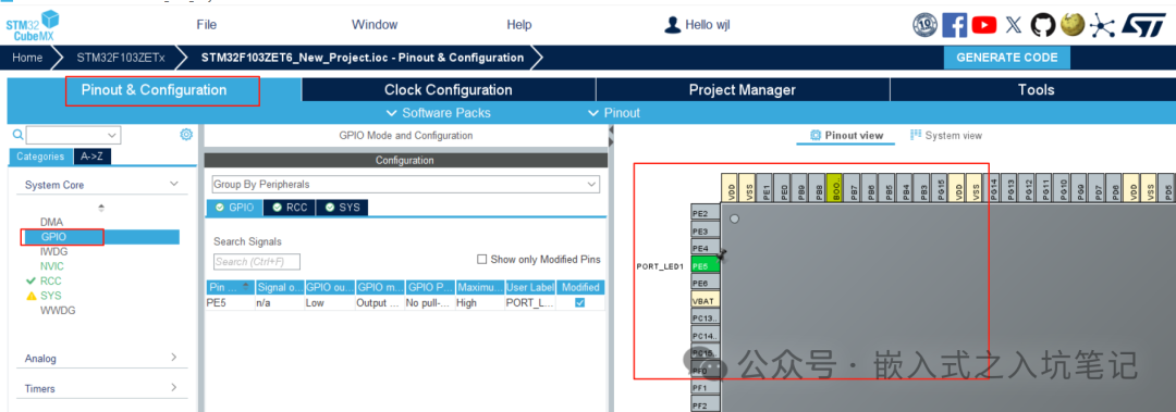 (2) Find the corresponding GPIO number, click on it, and a dropdown box will appear:
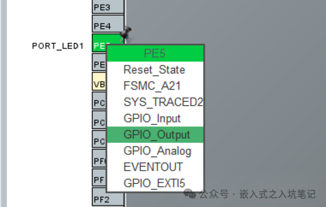 The options here determine the function to which the GPIO is configured.I set the GPIO to output mode by selecting GPIO_Output.(3) Set the options for the GPIO. As shown in the figure below:
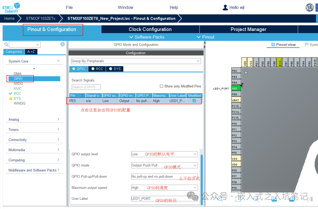 (4) After configuration, the GPIO still cannot output. You need to add some code in the code section, as follows:
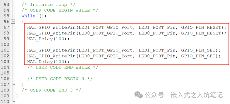 2. GPIO Input Configuration(1) For input, I chose PF1, and the input configuration is as follows:
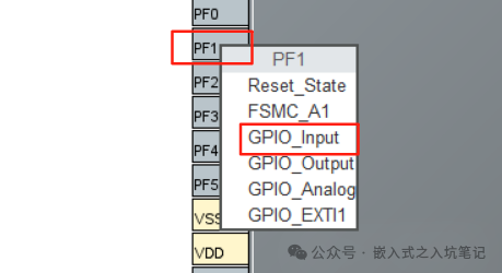 (2) The corresponding configuration is as follows:
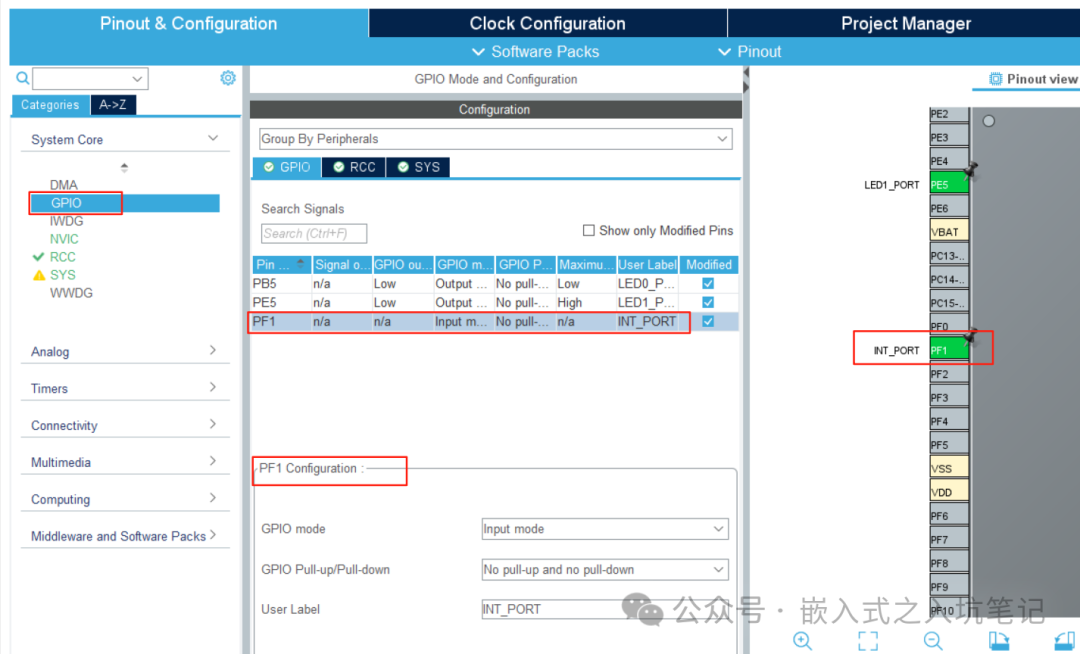 (3) Read the IO voltage level state:The API function needed to read the IO voltage level state is:
HAL_GPIO_ReadPin(GPIO_TypeDef *GPIOx, uint16_t GPIO_Pin)As follows:
HAL_GPIO_ReadPin(GPIOF, GPIO_Pin_7);This concludes the configuration and usage of GPIO for input/output.