Click the blue text
Follow 【51 Steel】
Enhanced Bottom Anode Monitoring in DC Electric Arc Furnaces Using Fiber-Optic SensorsFiber-optic sensors monitor the bottom electrode of DC electric arc furnaces. The pin-type bottom electrode is installed with conductive steel rods in the tamped material at the bottom of the furnace shell, used in high-power DC electric arc furnaces. Monitoring the wear of the anode during operation is crucial, as the cost of anode replacement is high and affects the productivity of the furnace. Steel liquid penetrating into the un-sintered refractory material layer can lead to a rapid increase in power slope, causing a drop in furnace temperature or prolonging the anode handling time when replacing the furnace shell. In extreme cases, when the anode wears too close to the lower furnace shell, molten steel may penetrate to the furnace bottom, which is an extremely dangerous phenomenon that must be avoided. The latest technology for monitoring bottom anode wear involves embedding thermocouples into the anode pins at various points. However, this method is not sensitive enough to detect localized damage to the anode, especially when cracks occur. This work utilizes fiber-optic sensors to monitor the health of the anode by creating a real-time spatial temperature distribution map of the anode. Unlike traditional thermocouples, these sensors can be installed at greater depths, provide distributed temperature measurements, and can withstand temperatures up to 900°C. Additionally, they can measure temperature at a collection rate of 5 Hz with a spatial resolution of 1.3 mm, providing unprecedented high-density real-time monitoring of anode health and improving the efficiency and safety of EAF operations.
Introduction
Electric arc furnaces account for approximately 70% of steel production in the United States, characterized by the use of electricity and recycled scrap steel, reducing carbon emissions. Although its energy efficiency ranges between 45% and 60%, there is still potential for further optimization. However, the parameters required for optimization exceed current monitoring capabilities. The effective operation of electric arc furnaces largely depends on the integrity and performance of critical components, especially the bottom anode structure of DC electric arc furnaces.[2]The design of bottom anodes varies widely,[3]however, this study focuses on a specific design of bottom anodes consisting of pins embedded in refractory material, connected to the power supply of the EAF, through the molten steel pool to the bottom electrode,[4]the wear condition of the bottom anode and the integrity of the electrode directly affect the production efficiency and safety of the furnace, making monitoring the state of the bottom anode crucial.Traditional methods for assessing the health of bottom anodes rely on single-point temperature measurements using thermocouples embedded in the anode pins.[2,5~8]This method has limitations in providing comprehensive insights into the condition of the refractory material and the interface between the anode and the molten steel pool. Moreover, this method must rely on forecasted temperature curves.[9]In electric arc furnaces, monitoring the bottom anode is critical for the circuit required for stable arcs in the furnace,[10]these arcs are generated between the bottom anode and the upper graphite electrode, forming the fundamental situation of the steelmaking process, thus the normal operation of the bottom anode is essential for the efficient operation of DC electric arc furnaces.In recent years, advancements in sensor technology, particularly the emergence of fiber-optic sensors, have opened new avenues for monitoring various components in the steelmaking process.[11,12]Unlike traditional thermocouples, fiber-optic sensors are compact, provide real-time distributed temperature monitoring, have the ability to resist electromagnetic interference (EMI), and are compatible with high-pressure, high-magnetic field environments, seamlessly integrating with control systems in scientific and industrial applications.[13~17]This presents an opportunity to overcome the limitations of conventional monitoring methods, allowing for a more accurate and comprehensive understanding of the condition of the bottom anode electrode.Figure1 illustrates a schematic of a standard single-mode fiber, including a medium waveguide with a core made of germanium-doped silica, wrapped in a silica cladding. The outer layer consists of a polymer coating, typically made of acrylate or polyimide, to enhance the mechanical durability of the fiber. When combined with fiber Bragg grating (FBG) technology, this commercially available fiber can serve as a distributed temperature sensor.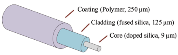 Figure1 Standard single-mode fiber for distributed temperature sensing [18]
Fiber Bragg Grating Sensing Technology
Fiber Bragg grating sensing technology represents a potential advancement in temperature monitoring in industrial environments, offering higher precision and reliability. Utilizing the properties of fiber optics, fiber Bragg grating (FBG) sensors consist of a periodically etched structure (known as a grating) embedded within the fiber core. When exposed to a temperature-changing environment, this grating experiences periodic slight changes, resulting in a shift in the reflected light wavelength along the fiber, as shown in Figure 2. By precisely measuring these wavelength shifts, FBG sensors can accurately determine temperature changes with high resolution and sensitivity.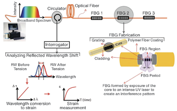 Figure2 Fiber Bragg grating (FBG) sensing technology[19]FBG sensors also exhibit excellent durability against electromagnetic interference and vibration, making them ideal for harsh environments such as electric arc furnaces. This technology provides new means for monitoring bottom anode wear, offering necessary real-time temperature data to optimize furnace performance, ensure operational safety, and maximize productivity.The expression for the Bragg wavelength λB is given by:[20]
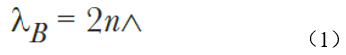 wheren is the refractive index of the core, and ∧ is the grating period.For an input light source with a working wavelength of λ, the change in λB due to a temperature change ΔT is expressed as:
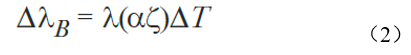 whereα is the thermal expansion coefficient of the fiber, and ζ is the thermo-optic coefficient of the fiber.This paper details the progress made in implementing fiber-optic temperature sensing based on fiber Bragg grating sensing technology on the bottom anode pins of industrial electric arc furnaces (EAF). The effectiveness of this measurement technology in capturing temperature readings on the anode pins indicates its potential for monitoring the cyclic thermal load on the anode pins,[21]and determining the efficiency of the anode cooling system, several mathematical models have been established[4,21 – 23] to study the temperature distribution of the bottom anode of the electric arc furnace. Since thermocouples are placed away from the induction current area,[23] validating the temperature distribution of these models is challenging. However, since fiber optics are unaffected by electromagnetic interference and can obtain measurements from these induction current areas, determining the temperature distribution of the bottom anode will be valuable.
Methods
Laboratory Experiments
Experiments were conducted in the laboratory to evaluate the performance of the fiber-optic channel configuration, simulating the expected conditions of the bottom anode pins in an industrial EAF environment. Since it is not feasible to fully replicate the conditions of industrial production electric arc furnace bottom electrodes, a simulated testing approach was adopted.
Testing Apparatus
This study used a box furnace as the experimental apparatus to create a controlled environment conducive to evaluating the robustness and signal quality of the fiber-optic channel configuration at high temperatures. The fiber-optic channel structure consists of single-mode fiber (SMF) with a polymer coating, wrapped in a fine silica tube (inner diameter 0.53 mm, wall thickness 0.14 mm), which is further wrapped in a stainless steel (SS) tube (inner diameter 1.12 mm, wall thickness 0.15 mm). To ensure safety, a glass fiber sleeve was used to connect the silica tube to the stainless steel tube below the pin, creating an open circuit in the circuit to mitigate any potential electric shock hazards from leakage current between the anode and the data collection system. The experimental setup in the steel mill adopted a similar configuration.
Testing Procedure
In the box furnace, the fiber-optic channel was securely placed next to the thermocouple for comparison. The furnace temperature was gradually raised to 900°C to test the robustness and performance of each component of the fiber-optic channel configuration at high temperatures. The experimental setup also allowed for the evaluation of signal quality when the fiber was subjected to different bending radii, simulating potential bending situations encountered when measuring the anode pins through the lower furnace shell.
Steel Mill Trials
After successful validation through laboratory testing, subsequent research involved applying the technology in steel mill trials. The aim was to verify and optimize the deployment of fiber-optic sensors on several outer bottom anode pins, which could be easily installed. All mill trials were conducted on a 150-ton DC electric arc furnace at Big River Steel in Osceola, Arkansas. These trials focused on demonstrating temperature measurements of the bottom anode and utilizing these measurements to calculate thermal flow and cooling system efficiency throughout the production process in the furnace, thereby recording the thermal distribution of the EAF under different operating conditions. During this implementation process in the steel mill, single-mode fiber with FBG sensors was deployed. These sensors can perform precise measurements at high temperatures of 900°C, but the space provided on-site is limited, typically capturing temperature data at only a few predetermined locations along the fiber length. However, FBGs can provide uninterrupted temperature data even under extreme working conditions. To ensure the precise placement of the sensors, a 1.14 mm square groove was machined into the lower half of the anode pin, as shown in Figure 4. This groove serves as a fixed point space for embedding the fiber, which is wrapped in a fine silica tube and then securely wrapped in a stainless steel (SS) tube for added durability and protection. Refractory mud was then applied to secure the embedded fiber within the SS tube, placed in the groove of the anode pin. Within this fiber-optic channel, three FBG sensors were fabricated at predetermined positions: FBG-1 located 7 inches from the anode base, while FBG-2 and FBG-3 are located at heights of 5 inches and 3 inches, respectively. Additionally, each anode pin is also equipped with a thermocouple to continuously capture temperature measurements 4 inches from the anode base. After inspecting the pins, the entire anode section was reinstalled onto the lower furnace maintenance rack, the anode assembly was installed into the furnace shell, and filled with the lower furnace refractory material. When replacing the furnace shell, the lower furnace was transported to the melting operation position within the electric furnace workshop. Throughout the experiment, temperature measurements from all three FBG sensors were recorded every second. Data collection was conducted in two phases: (1) Initial data collection over a running time of more than 10 days, averaging 40 heats per day, providing a comprehensive dataset; (2) The second data collection was planned to occur at the end of the EAF activity, with the furnace producing approximately 1050 hours. However, due to an unrelated computer system failure, only one hour of temperature measurements could be recorded at the end of the activity.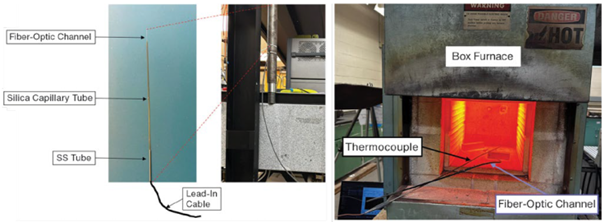 Figure3 Laboratory testing of fiber-optic sensor configuration using a box furnace
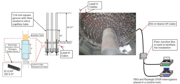 Figure4 Fiber-optic channel configuration and installation on the bottom anode pin of the electric arc furnace
Results and Discussion
The laboratory tests of the fiber-optic sensors under simulated industrial site conditions demonstrated the functionality of temperature measurements and the fiber sheath structure. Figure 5 shows the smooth temperature curves recorded by the FBG sensors during these tests. To balance signal robustness and ease of installation, the maximum temperature of the introducing cable extending from the pin to the EAF anode section was 800°C, with an optimal bending angle of 45° for subsequent industrial trials. The stability tests shown in Figure 5 confirmed the reliability of the fiber-optic channel configuration in subsequent temperature measurements of the anode pins in industrial electric arc furnaces.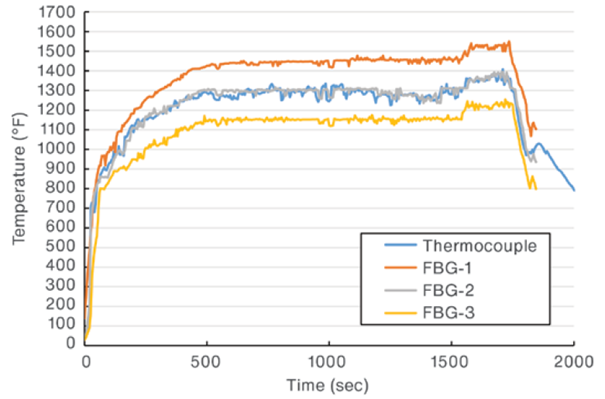 Figure5 Stability test of the fiber Bragg grating (FBG) sensor fiber channel structure The factory trials at Big River Steel – U.S. Steel’s 150-ton DC electric arc furnace demonstrated that the fiber sheath design effectively protected the fiber from damage and deformation during the tamping of the bottom anode refractory material. Furthermore, the instrumentation anode section was successfully repositioned without damaging the fiber, introducing a 30-meter long cable at the lower furnace maintenance station, and subsequently safely protecting the fiber cable when the furnace was replaced, transferring the lower furnace to the melting operation position in the electric furnace workshop. Using a 1 Hz data collection rate and a fiber-optic channel consisting of three FBG sensors located at predetermined different heights, the initial data collection time exceeded 10 days, averaging 40 heats per day, providing a comprehensive dataset for subsequent analysis. After 38.5 days of continuous operation and several planned maintenance activities, the second data collection process was initiated, continuing until the end of an EAF cycle, to verify the durability of the fiber-optic sensors, lasting approximately 1,050 hours. In Figure 6a, data from one of the measuring pins equipped with three FBG sensors is presented. Additionally, Figure 6b illustrates the correlation observed between temperature fluctuations in the FBG sensor and thermocouple measurements, consistent with variations in electric power input and operational cycles of the furnace. Figure 6c shows an enlarged view of the highlighted area in Figure 6a, confirming the resilience of the fiber under the harsh conditions of the entire electric furnace smelting process.
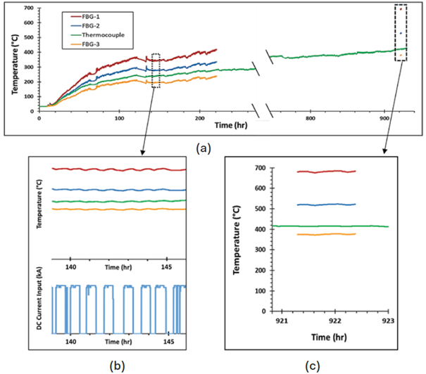 Figure6 FBG temperature measurement data compared with anode thermocouple data shows:220 hours of FBG and thermocouple data(a) , temperature fluctuations correlated with input DC current(b) , and at the end of the furnace cycle1.5 hours of data(c)
Conclusion
The demonstration of fiber-optic sensors for monitoring the bottom anode of electric furnaces shows promise for improving the efficiency and safety of the steelmaking process. The steel mill trials conducted at Big River Steel (U.S. Steel) showcased the successful deployment and effective operation of fiber-optic sensors on the EAF. Notably, the installation and securing of fiber-optic sensors on the anode pins withstood the tamping of the bottom refractory material, transportation and replacement of the furnace shell, and operation throughout the entire furnace campaign, proving the feasibility of the technology. The intervals of temperature measurements and their correlation with electric power input indicate that fiber-optic sensors can also be used to assess the operating conditions of the furnace. Further research and applications could enhance process control in electric arc furnace smelting, improve operational efficiency, and elevate safety protocols.
Future Work
The temperature data provided by fiber-optic sensors will be used in future work to calculate the total heat flux density through the bottom anode. This data will enable a more accurate estimation of the temperature distribution along the anode pins and adjacent refractory layers, tracking and predicting the wear of the lower furnace refractory materials during the electric furnace operation. Through these measurements, a deeper understanding of the dynamic thermal conditions within the furnace can be achieved, improving refractory wear and enhancing operational performance.
Acknowledgments
This work was supported by the U.S. Department of Energy’s Office of Energy Efficiency and Renewable Energy (EERE) under Award Number DE-EE0009392. The views expressed in this paper do not necessarily represent the views of the U.S. Department of Energy or the U.S. government.
51 Steel Resource Library
Copyright Statement:This article is sourced from Tang Jiemin’s 40 years in metallurgy, organized and published by #51 Steel, with copyright belonging to the original author. Please indicate the source when reprinting; if there are any biases in the article content, please kindly point them out; if the source is incorrectly marked or infringes copyright, please contact us.Welcome to follow the WeChat public account 【51 Steel】 ID: Steel-51, welcome cooperation: 19863724554.
Click “Read the original text” to see more exciting content!