● Interrupts
Interrupts play a very important role in microcontrollers. The code executes from top to bottom by default, and when it encounters conditions or other statements, it jumps to specified locations. During the execution of code in a microcontroller, unexpected situations may arise that need to be handled, which will interrupt the current code. After handling the unexpected situation, the program will return to the interrupted point and continue execution.
● About STM32 Interrupts
Almost every microcontroller has interrupts. For example, the STM32F407VE is a chip based on the Cortex-M4 core, which has some management for interrupts in the CM4 core, and there is also some management for interrupts in STM32 chips. Therefore, we can summarize that STM32 interrupts are controlled by two layers of controllers. If you want to use interrupts, you must configure both the core and the chip.
● CM4 Core Interrupts
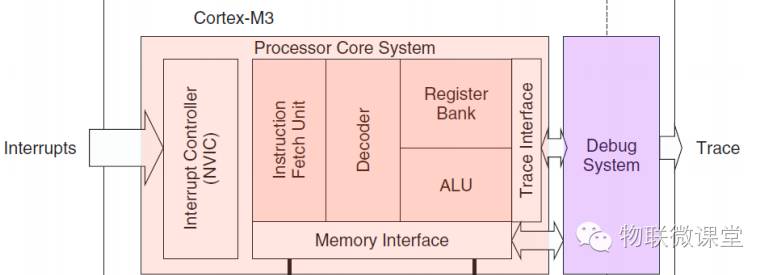 From the core architecture diagram, we can see that the NVIC controller manages interrupts in the core. The core’s control over interrupts mainly manifests in several aspects: interrupt addresses, interrupt priorities, and interrupt enabling.
1. Interrupt Addresses
The execution of a program involves seeking addresses, and interrupts are part of the program, but their addresses are determined by the core and cannot be modified. The NVIC controller helps us find the interrupt addresses.
2. Interrupt Priorities
Priority is a very important concept in interrupts. If multiple interrupts occur simultaneously, the CPU will choose the order of handling these interrupts based on their priorities. In the CM4 core, priorities are represented by integers, with smaller numbers indicating higher levels.
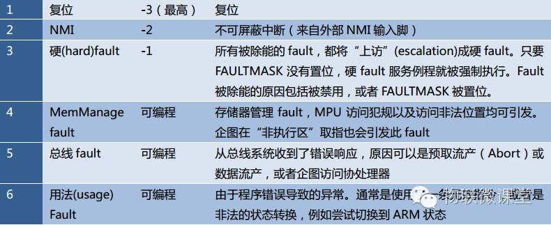 From the CM4 core manual, we can see that the reset interrupt has the highest priority and cannot be modified. You should be able to guess this; in the computer world, nothing has a higher level than reset.
The NVIC controller’s control over priorities is divided into two levels: preemption priority and sub-priority. When multiple interrupts occur simultaneously, the one with a higher preemption priority executes first, and if the preemption priorities are the same, the one with a higher sub-priority executes first.
The settings for preemption priority and sub-priority are determined by an 8-bit register (IPR). The NVIC controller divides this 8-bit register into two halves, with the high bits controlling preemption priority and the low bits controlling sub-priority.
There is also a register in the NVIC controller (ARICR[10:8]) that determines how the 8-bit priority register (IPR) is divided into two halves. We know that ARICR[10:8] can represent 0-7, and the following table shows the relationship between ARICR[10:8] and IPR.
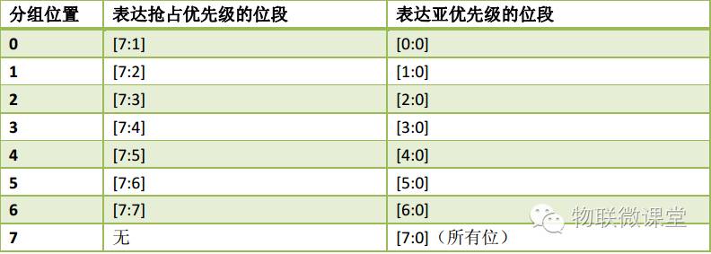 Note: Although the above image shows the grouping relationship of priorities, the STM32 chip does not use all bits of the priority register. For example, the STM32F407VE uses the high 4 bits to represent priority. If ARICR[10:8]=5, the table above indicates that [7:6] represents preemption priority and [5:4] represents sub-priority. A CPU can have N interrupts, each with its own configurable priority, but interrupt priority grouping is singular. For example, if we set the priority grouping of STM32F407VE to 5, then all interrupts’ preemption priorities are controlled by 2 bits, and sub-priorities are also controlled by 2 bits.
3. Interrupt Enabling
NVIC has overall control over interrupts, so there is a switch here to determine whether the interrupt function can be enabled.
● STM32 External Interrupts
External interrupts are just one type of interrupt, generally triggered by changes in the level signal of the IO port. STM32 has 23 edge detectors for generating events/interrupt requests. Each input line can be configured individually, allowing you to choose the type (interrupt or event) and the corresponding trigger event (rising edge, falling edge, or edge-triggered). Each line can also be configured individually.
1. Interrupt Framework
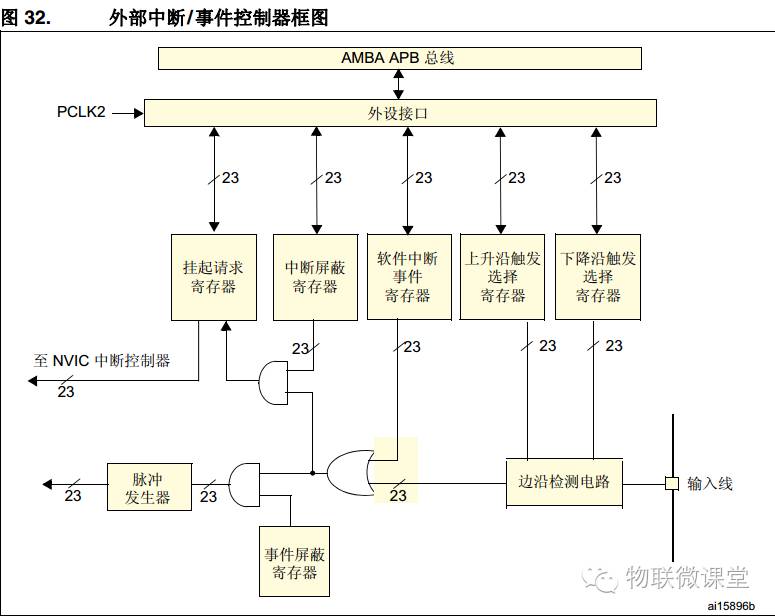 From the above image, we can see the configuration method for external interrupts:
1) Enable the corresponding APB clock
2) Select the external interrupt input line
3) Set the interrupt trigger method
4) Choose the operating mode (external interrupt or event)
5) Enable
2. External Interrupt Selection
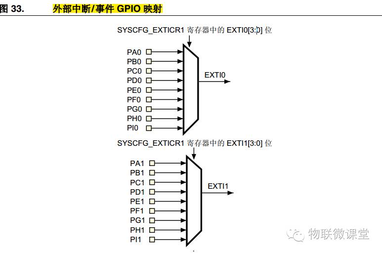
The above image lists the relationship between external interrupt lines and GPIO pins, summarizing that external interrupt x is connected to GPIOx. For example, when we use external interrupt 0, it can be configured to connect with one or several of PA0~PI0.
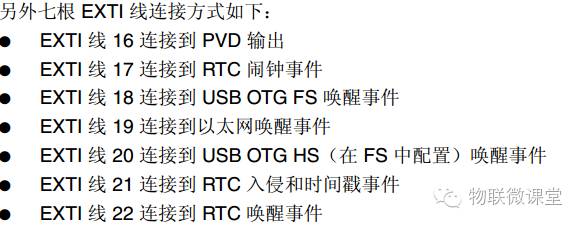
GPIO has 16 pins, using a total of 16 external interrupts, but where are the remaining 7 interrupts? Please see the following image. From the image, we can understand that the other 7 interrupts belong to the “event” type.
3. Registers
EXTI_IMR Interrupt Mask Register
EXTI_EMR Event Mask Register
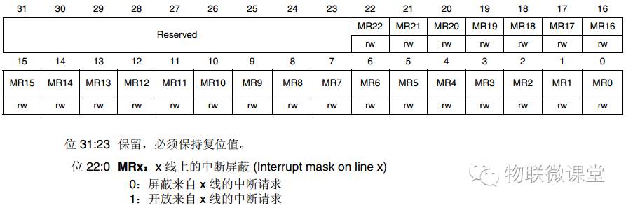
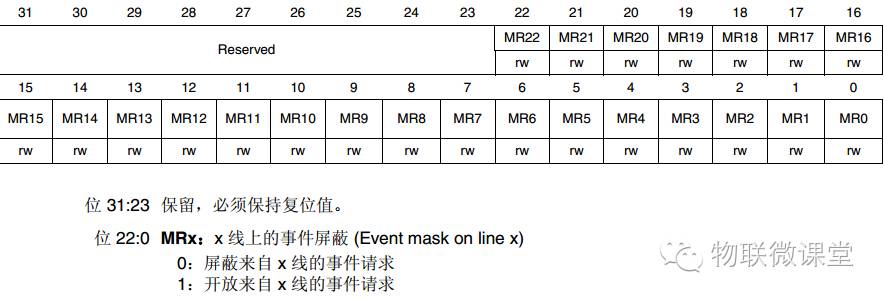 This is the switch for interrupts or events; only when the corresponding bit is set to 1 can the interrupt or event take effect.
EXTI_RTSR Rising Edge Selection RegisterEXTI_FTSR Falling Edge Selection Register
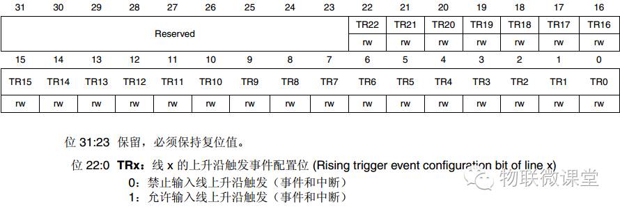
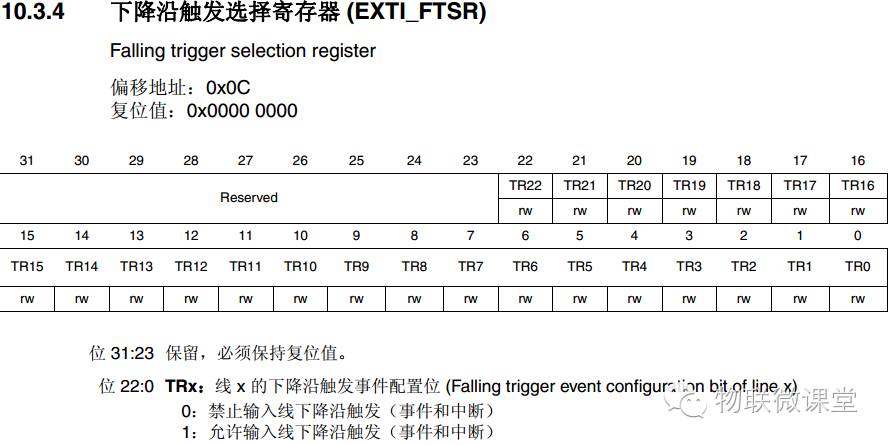 These two registers are used to select the trigger type for interrupts/events, which can be rising edge, falling edge, or edge-triggered (both rising and falling can trigger).
EXTI_PR Interrupt Pending Register
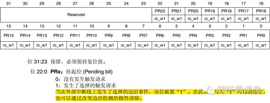 This register is a flag; if it is 1, it indicates that the corresponding external interrupt has occurred. It should be noted that this register needs to be manually cleared.
● From Manual to Process
From the above description, we can summarize the configuration method for external interrupts (in fact, all interrupt configurations are similar).
1. STM32 Chip Interrupt Settings
1) Enable the clock
2) Select the interrupt pin
3) Select the interrupt mode
4) Select the interrupt trigger method
5) Enable the interrupt
2. CM4 Core Interrupt Configuration
1) Interrupt priority grouping (how many bits represent preemption priority, how many bits represent sub-priority)
2) Set the interrupt address
3) Set the preemption priority
4) Set the sub-priority
5) Enable the interrupt
● From Process to Code (Using Button Interrupt as an Example, Using Library Functions)
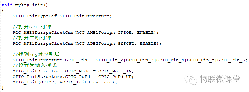
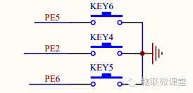 When using external interrupts, first ensure that the GPIO is in input mode; only in input mode can external signals enter the CPU and trigger the interrupt.
1. GPIO Configuration
 2. Interrupt Configuration (There are 2 parts)
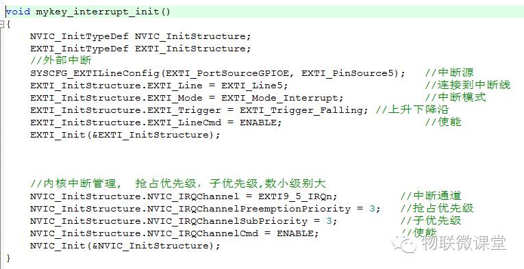 3. Global interrupt grouping settings; this line of code needs to be written in the main function.
