Reminder: This article provides a detailed analysis of the functions related to GPIO configuration in the HAL library, including MX_GPIO_Init(), HAL_GPIO_WritePin(), and HAL_GPIO_Init(). At the end of the article, a description of the f1 series GPIO port registers is attached.
MX_GPIO_Init()
First, let’s look at the source code:
void MX_GPIO_Init(void){
  GPIO_InitTypeDef GPIO_InitStruct = {0};
  /* GPIO Ports Clock Enable */  __HAL_RCC_GPIOD_CLK_ENABLE();  __HAL_RCC_GPIOC_CLK_ENABLE();  __HAL_RCC_GPIOA_CLK_ENABLE();
  /*Configure GPIO pin Output Level */  HAL_GPIO_WritePin(LED4_GPIO_Port, LED4_Pin, GPIO_PIN_SET);
  /*Configure GPIO pin : PtPin */  GPIO_InitStruct.Pin = LED4_Pin;  GPIO_InitStruct.Mode = GPIO_MODE_OUTPUT_PP;  GPIO_InitStruct.Pull = GPIO_NOPULL;  GPIO_InitStruct.Speed = GPIO_SPEED_FREQ_LOW;  HAL_GPIO_Init(LED4_GPIO_Port, &GPIO_InitStruct);
}
Next, let’s analyze the code line by line.
void MX_GPIO_Init(void){ GPIO_InitTypeDef GPIO_InitStruct = {0};This defines a function named MX_GPIO_Init with no input parameters and no return value. It also creates a structure variable of type GPIO_InitTypeDef named GPIO_InitStruct and initializes it to zero.
__HAL_RCC_GPIOD_CLK_ENABLE(); __HAL_RCC_GPIOC_CLK_ENABLE(); __HAL_RCC_GPIOA_CLK_ENABLE();By calling __HAL_RCC_GPIOD_CLK_ENABLE(), __HAL_RCC_GPIOC_CLK_ENABLE(), and __HAL_RCC_GPIOA_CLK_ENABLE(), the clocks for ports GPIOD, GPIOC, and GPIOA are enabled.
HAL_GPIO_WritePin(LED4_GPIO_Port, LED4_Pin, GPIO_PIN_SET);This line sets the output level of the LED4_Pin pin to high (GPIO_PIN_SET). It uses the HAL_GPIO_WritePin function provided by the HAL library.
GPIO_InitStruct.Pin = LED4_Pin; GPIO_InitStruct.Mode = GPIO_MODE_OUTPUT_PP; GPIO_InitStruct.Pull = GPIO_NOPULL; GPIO_InitStruct.Speed = GPIO_SPEED_FREQ_LOW; HAL_GPIO_Init(LED4_GPIO_Port, &GPIO_InitStruct);These lines configure the mode, pull-up/pull-down, and speed of the pin LED4_Pin. First, LED4_Pin is assigned to GPIO_InitStruct.Pin, then the mode is set to output mode (GPIO_MODE_OUTPUT_PP), no pull-up/pull-down (GPIO_NOPULL), and low speed (GPIO_SPEED_FREQ_LOW). Finally, the configuration is applied to LED4_GPIO_Port by calling HAL_GPIO_Init.
In summary, the main function of the above code is to initialize the specified GPIO pin. It enables the clock for the corresponding port, sets the output level of a pin, and configures the mode, pull-up/pull-down, and speed of that pin. Thus, after calling this function, the relevant GPIO pins are correctly initialized and can be used for subsequent input/output operations.
Some clever friends may ask: Why does the above code set the IO pin level before configuring the IO pin mode?
The answer: Before initializing the IO port, we need to ensure that the IO pin level is correct to avoid unexpected level changes after switching to output mode. If we set the mode first and then the level, it could lead to a momentary change in the IO pin level before switching to output mode, causing unnecessary interference or errors.
HAL_GPIO_WritePin()
Talk is cheap. Show me the code.
void HAL_GPIO_WritePin(GPIO_TypeDef *GPIOx, uint16_t GPIO_Pin, GPIO_PinState PinState){  /* Check the parameters */  assert_param(IS_GPIO_PIN(GPIO_Pin));  assert_param(IS_GPIO_PIN_ACTION(PinState));
  if (PinState != GPIO_PIN_RESET)  {    GPIOx->BSRR = GPIO_Pin;  }  else  {    GPIOx->BSRR = (uint32_t)GPIO_Pin << 16u;  }}
This code is the implementation of the HAL_GPIO_WritePin function in the HAL library. This function is used to set the output level of the specified GPIO pin.
Let’s analyze the functionality and operations of the code line by line:
void HAL_GPIO_WritePin(GPIO_TypeDef *GPIOx, uint16_t GPIO_Pin, GPIO_PinState PinState)This is the function definition, which accepts three parameters: GPIOx is a pointer to the GPIO port, GPIO_Pin is the GPIO pin to be set, and PinState is the output level to be set.
/* Check the parameters */ assert_param(IS_GPIO_PIN(GPIO_Pin)); assert_param(IS_GPIO_PIN_ACTION(PinState));These lines are for parameter checking, ensuring that the passed pin and level parameters are valid. assert_param() is an assertion macro used to check the legality of parameters during debugging.
if (PinState != GPIO_PIN_RESET) { GPIOx->BSRR = GPIO_Pin; } else { GPIOx->BSRR = (uint32_t)GPIO_Pin << 16u; }This is the main logic of the function. If PinState is not equal to GPIO_PIN_RESET, which means the output level to be set is high,
then the corresponding pin position in the GPIOx->BSRR register is set to 1, thereby setting the output level of the pin to high.
If PinState equals GPIO_PIN_RESET, meaning the output level to be set is low, then the corresponding pin position in GPIOx->BSRR is set to 1 (setting the pin to low), while the high 16 bits of GPIOx->BSRR are set to 1 (clearing the pin to high), thus setting the output level of the pin to low.
Through this logic, the output level of the GPIO pin can be set according to the value of PinState.
In summary, the above code implements the HAL_GPIO_WritePin function, which is used to set the output level of the specified GPIO pin. By judging the value of PinState, it sets the corresponding bits of the GPIO register to high or low, thus achieving the setting of the output level.
HAL_GPIO_Init()
Due to the length of this function, the source code will be placed after the analysis, omitting unimportant parts.
uint32_t position = 0x00u; uint32_t ioposition; uint32_t iocurrent; uint32_t temp; uint32_t config = 0x00u; __IO uint32_t *configregister; uint32_t registeroffset;position: Used to track the current pin position being processed. It increments in the loop to process the next pin.
ioposition: Used to obtain the bit position of the current pin. Obtained by shifting position.
iocurrent: By performing a bitwise AND operation between GPIO_Init->Pin and ioposition, it checks whether the current pin needs to be initialized. If iocurrent equals ioposition, it indicates that the current pin needs to be initialized.
temp: A temporary variable.
config: Used to store the configuration value of the pin. Based on different modes and parameters, the corresponding configuration value is written to this variable.
configregister: Used to store a pointer to either the CRL or CRH register, depending on the pin number range. This pointer will be used to modify the register values in subsequent code.
registeroffset: Used as an offset when calculating the positions of CNF and MODE bits in the CRL or CRH register.
while (((GPIO_Init->Pin) >> position) != 0x00u)  {    /* Get the IO position */    ioposition = (0x01uL << position);
    /* Get the current IO position */    iocurrent = (uint32_t)(GPIO_Init->Pin) & ioposition;
    if (iocurrent == ioposition)    {      /* Check the Alternate function parameters */      assert_param(IS_GPIO_AF_INSTANCE(GPIOx));
      /* Based on the required mode, filling config variable with MODEy[1:0] and CNFy[3:2] corresponding bits */      switch (GPIO_Init->Mode)      {        /* If we are configuring the pin in OUTPUT push-pull mode */        case GPIO_MODE_OUTPUT_PP:        assert_param(IS_GPIO_SPEED(GPIO_Init->Speed));          config = GPIO_Init->Speed + GPIO_CR_CNF_GP_OUTPUT_PP;          break;        ....
Let’s analyze the above code segment line by line:
while (((GPIO_Init->Pin) >> position) != 0x00u)This is the start of a loop. It determines whether to continue executing the loop by checking if the value of (GPIO_Init->Pin) right-shifted by position is not equal to 0. GPIO_Init->Pin is a bitmask representing the pin status, and by right-shifting position, it checks the status of each pin.
ioposition = (0x01uL << position);This line calculates the current pin position. It uses bit manipulation to left-shift 1 by position and stores the result in the ioposition variable. This results in a value where only the position bit is 1, and all other bits are 0.
iocurrent = (uint32_t)(GPIO_Init->Pin) & ioposition;This line retrieves the current pin status. It casts GPIO_Init->Pin to uint32_t and performs a bitwise AND operation with ioposition, storing the result in the iocurrent variable. This checks if the current pin’s status is 1.
if (iocurrent == ioposition)This is a conditional statement that checks if the current pin needs to be initialized. If the current pin’s status equals the value of ioposition, meaning the current pin’s status is 1, it enters the conditional check.
assert_param(IS_GPIO_AF_INSTANCE(GPIOx));This is an assertion macro that checks whether GPIOx is a valid GPIO peripheral instance. If GPIOx does not meet the condition (i.e., it is not a valid GPIO peripheral instance), it triggers an assertion error.
switch (GPIO_Init->Mode)This is a switch statement that performs multiple branch checks based on the value of GPIO_Init->Mode, which indicates the mode of the current pin.
case GPIO_MODE_OUTPUT_PP: assert_param(IS_GPIO_SPEED(GPIO_Init->Speed)); config = GPIO_Init->Speed + GPIO_CR_CNF_GP_OUTPUT_PP; break;This branch handles the case where the pin is configured in output push-pull mode (GPIO_MODE_OUTPUT_PP). In this branch, it checks the GPIO speed parameter, and then calculates the value of config based on the speed parameter and the corresponding control register configuration value.
In summary, they form a loop structure used to iterate through a set of pin statuses and perform initialization configurations as needed. In each loop iteration, the current pin’s position and status are obtained, and conditional checks and configuration operations are performed based on the status.
      /* Check if the current bit belongs to first half or last half of the pin count number in order to address CRH or CRL register*/      configregister = (iocurrent < GPIO_PIN_8) ? &GPIOx->CRL     : &GPIOx->CRH;      registeroffset = (iocurrent < GPIO_PIN_8) ? (position << 2u) : ((position - 8u) << 2u);
      /* Apply the new configuration of the pin to the register */      MODIFY_REG((*configregister), ((GPIO_CRL_MODE0 | GPIO_CRL_CNF0) << registeroffset), (config << registeroffset));
This segment of code is mainly used to apply the pin’s configuration to the corresponding register. Here is a detailed analysis of the code:
First, the code checks whether the current bit belongs to the first half (less than 8) or the last half (greater than or equal to 8) of the pin count number. This is because in the register, the configuration bits for pins 0 to 7 are located in the Control Register Low (CRL), while those for pins 8 to 15 are located in the Control Register High (CRH).
Using the ternary conditional operator, configregister is set to point to either the CRL or CRH register, depending on the range of the pin number iocurrent. Similarly, registeroffset is set to the corresponding register offset. If iocurrent is less than 8, it indicates that the pin belongs to the first half, and the register offset is position left-shifted by 2; otherwise, the pin belongs to the second half, and the offset is (position – 8u) left-shifted by 2.
Next, the code uses the MODIFY_REG macro to apply the new configuration to the register. The MODIFY_REG macro is used to modify specific bit fields of a register, with parameters including the register to modify, the bit field to modify, and the new value to write to the bit field.
In this case, the expression (*configregister) dereferences the configregister pointer to obtain the register to modify. The expression ((GPIO_CRL_MODE0 | GPIO_CRL_CNF0) << registeroffset) calculates the mask for the bits to be modified, left-shifting the configuration value by registeroffset bits and ORing it with GPIO_CRL_MODE0 and GPIO_CRL_CNF0. config << registeroffset is the new configuration value to be written to the bit field.
By using the MODIFY_REG macro, the code writes the new pin configuration to the appropriate register bit field, thus updating the pin’s configuration.
 if ((GPIO_Init->Mode & EXTI_MODE) == EXTI_MODE)      {        /* Enable AFIO Clock */        __HAL_RCC_AFIO_CLK_ENABLE();        temp = AFIO->EXTICR[position >> 2u];        CLEAR_BIT(temp, (0x0Fu) << (4u * (position & 0x03u)));        SET_BIT(temp, (GPIO_GET_INDEX(GPIOx)) << (4u * (position & 0x03u)));        AFIO->EXTICR[position >> 2u] = temp;

        /* Enable or disable the rising trigger */        if ((GPIO_Init->Mode & RISING_EDGE) == RISING_EDGE)        {          SET_BIT(EXTI->RTSR, iocurrent);        }        else        {          CLEAR_BIT(EXTI->RTSR, iocurrent);        }
        /* Enable or disable the falling trigger */        if ((GPIO_Init->Mode & FALLING_EDGE) == FALLING_EDGE)        {          SET_BIT(EXTI->FTSR, iocurrent);        }        else        {          CLEAR_BIT(EXTI->FTSR, iocurrent);        }
        /* Configure the event mask */        if ((GPIO_Init->Mode & GPIO_MODE_EVT) == GPIO_MODE_EVT)        {          SET_BIT(EXTI->EMR, iocurrent);        }        else        {          CLEAR_BIT(EXTI->EMR, iocurrent);        }
        /* Configure the interrupt mask */        if ((GPIO_Init->Mode & GPIO_MODE_IT) == GPIO_MODE_IT)        {          SET_BIT(EXTI->IMR, iocurrent);        }        else        {          CLEAR_BIT(EXTI->IMR, iocurrent);        }
      }    }
This segment of code is used to configure the external interrupt settings related to GPIO. Let’s analyze the functionality of this code line by line:
First, it checks whether to configure the external interrupt by performing a bitwise AND operation between GPIO_Init->Mode and EXTI_MODE to see if the result equals EXTI_MODE. EXTI_MODE is a macro definition representing the external interrupt mode.
If external interrupt configuration is needed, the AFIO (Alternate Function I/O) clock is first enabled. AFIO is a peripheral used to manage GPIO’s multiplexing functions.
Next, it reads the corresponding value from the AFIO EXTICR register for the current position.
Based on GPIOx (GPIO port number) and position (GPIO pin number), it calculates the value to be set and assigns it to temp.
The value of temp is then written to the AFIO EXTICR register to complete the external interrupt configuration.
Based on the result of the bitwise AND operation between GPIO_Init->Mode and RISING_EDGE, it determines whether to enable the rising edge trigger interrupt. If needed, it sets the corresponding bit in the EXTI RTSR register.
Similarly, based on the result of the bitwise AND operation between GPIO_Init->Mode and FALLING_EDGE, it determines whether to enable the falling edge trigger interrupt. If needed, it sets the corresponding bit in the EXTI FTSR register.
It also checks whether to configure the event mask based on GPIO_Init->Mode and GPIO_MODE_EVT. If needed, it sets the corresponding bit in the EXTI EMR register.
Finally, it checks whether to configure the interrupt mask based on GPIO_Init->Mode and GPIO_MODE_IT. If needed, it sets the corresponding bit in the EXTI IMR register.
void HAL_GPIO_Init(GPIO_TypeDef  *GPIOx, GPIO_InitTypeDef *GPIO_Init){  uint32_t position = 0x00u;  uint32_t ioposition;  uint32_t iocurrent;  uint32_t temp;  uint32_t config = 0x00u;  __IO uint32_t *configregister; /* Store the address of CRL or CRH register based on pin number */  uint32_t registeroffset;       /* offset used during computation of CNF and MODE bits placement inside CRL or CRH register */
  /* Check the parameters */  assert_param(IS_GPIO_ALL_INSTANCE(GPIOx));  assert_param(IS_GPIO_PIN(GPIO_Init->Pin));  assert_param(IS_GPIO_MODE(GPIO_Init->Mode));
  /* Configure the port pins */  while (((GPIO_Init->Pin) >> position) != 0x00u)  {    /* Get the IO position */    ioposition = (0x01uL << position);
    /* Get the current IO position */    iocurrent = (uint32_t)(GPIO_Init->Pin) & ioposition;
    if (iocurrent == ioposition)    {      /* Check the Alternate function parameters */      assert_param(IS_GPIO_AF_INSTANCE(GPIOx));
      /* Based on the required mode, filling config variable with MODEy[1:0] and CNFy[3:2] corresponding bits */      switch (GPIO_Init->Mode)      {        /* If we are configuring the pin in OUTPUT push-pull mode */        case GPIO_MODE_OUTPUT_PP:          /* Check the GPIO speed parameter */          assert_param(IS_GPIO_SPEED(GPIO_Init->Speed));          config = GPIO_Init->Speed + GPIO_CR_CNF_GP_OUTPUT_PP;          break;
        /* If we are configuring the pin in OUTPUT open-drain mode */        case GPIO_MODE_OUTPUT_OD:          /* Check the GPIO speed parameter */          assert_param(IS_GPIO_SPEED(GPIO_Init->Speed));          config = GPIO_Init->Speed + GPIO_CR_CNF_GP_OUTPUT_OD;          break;
        /* If we are configuring the pin in ALTERNATE FUNCTION push-pull mode */        case GPIO_MODE_AF_PP:          /* Check the GPIO speed parameter */          assert_param(IS_GPIO_SPEED(GPIO_Init->Speed));          config = GPIO_Init->Speed + GPIO_CR_CNF_AF_OUTPUT_PP;          break;
        /* If we are configuring the pin in ALTERNATE FUNCTION open-drain mode */        case GPIO_MODE_AF_OD:          /* Check the GPIO speed parameter */          assert_param(IS_GPIO_SPEED(GPIO_Init->Speed));          config = GPIO_Init->Speed + GPIO_CR_CNF_AF_OUTPUT_OD;          break;
        /* If we are configuring the pin in INPUT (also applicable to EVENT and IT mode) */        case GPIO_MODE_INPUT:        case GPIO_MODE_IT_RISING:        case GPIO_MODE_IT_FALLING:        case GPIO_MODE_IT_RISING_FALLING:        case GPIO_MODE_EVT_RISING:        case GPIO_MODE_EVT_FALLING:        case GPIO_MODE_EVT_RISING_FALLING:          /* Check the GPIO pull parameter */          assert_param(IS_GPIO_PULL(GPIO_Init->Pull));          if (GPIO_Init->Pull == GPIO_NOPULL)          {            config = GPIO_CR_MODE_INPUT + GPIO_CR_CNF_INPUT_FLOATING;          }          else if (GPIO_Init->Pull == GPIO_PULLUP)          {            config = GPIO_CR_MODE_INPUT + GPIO_CR_CNF_INPUT_PU_PD;
            /* Set the corresponding ODR bit */            GPIOx->BSRR = ioposition;          }          else /* GPIO_PULLDOWN */          {            config = GPIO_CR_MODE_INPUT + GPIO_CR_CNF_INPUT_PU_PD;
            /* Reset the corresponding ODR bit */            GPIOx->BRR = ioposition;          }          break;
        /* If we are configuring the pin in INPUT analog mode */        case GPIO_MODE_ANALOG:          config = GPIO_CR_MODE_INPUT + GPIO_CR_CNF_ANALOG;          break;
        /* Parameters are checked with assert_param */        default:          break;      }
      /* Check if the current bit belongs to first half or last half of the pin count number in order to address CRH or CRL register*/      configregister = (iocurrent < GPIO_PIN_8) ? &GPIOx->CRL     : &GPIOx->CRH;      registeroffset = (iocurrent < GPIO_PIN_8) ? (position << 2u) : ((position - 8u) << 2u);
      /* Apply the new configuration of the pin to the register */      MODIFY_REG((*configregister), ((GPIO_CRL_MODE0 | GPIO_CRL_CNF0) << registeroffset), (config << registeroffset));
      /*--------------------- EXTI Mode Configuration ------------------------*/      /* Configure the External Interrupt or event for the current IO */      if ((GPIO_Init->Mode & EXTI_MODE) == EXTI_MODE)      {        /* Enable AFIO Clock */        __HAL_RCC_AFIO_CLK_ENABLE();        temp = AFIO->EXTICR[position >> 2u];        CLEAR_BIT(temp, (0x0Fu) << (4u * (position & 0x03u)));        SET_BIT(temp, (GPIO_GET_INDEX(GPIOx)) << (4u * (position & 0x03u)));        AFIO->EXTICR[position >> 2u] = temp;

        /* Enable or disable the rising trigger */        if ((GPIO_Init->Mode & RISING_EDGE) == RISING_EDGE)        {          SET_BIT(EXTI->RTSR, iocurrent);        }        else        {          CLEAR_BIT(EXTI->RTSR, iocurrent);        }
        /* Enable or disable the falling trigger */        if ((GPIO_Init->Mode & FALLING_EDGE) == FALLING_EDGE)        {          SET_BIT(EXTI->FTSR, iocurrent);        }        else        {          CLEAR_BIT(EXTI->FTSR, iocurrent);        }
        /* Configure the event mask */        if ((GPIO_Init->Mode & GPIO_MODE_EVT) == GPIO_MODE_EVT)        {          SET_BIT(EXTI->EMR, iocurrent);        }        else        {          CLEAR_BIT(EXTI->EMR, iocurrent);        }
        /* Configure the interrupt mask */        if ((GPIO_Init->Mode & GPIO_MODE_IT) == GPIO_MODE_IT)        {          SET_BIT(EXTI->IMR, iocurrent);        }        else        {          CLEAR_BIT(EXTI->IMR, iocurrent);        }      }    }
    position++;  }
GPIO Related Registers
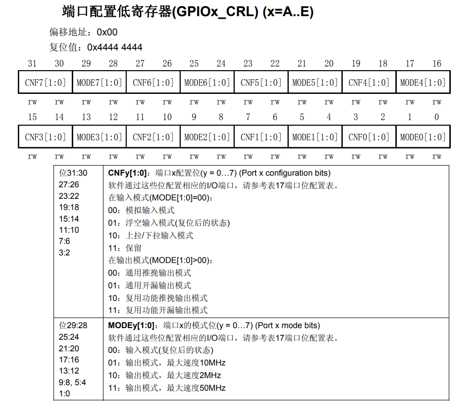
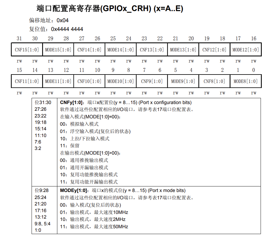
Port Configuration Register
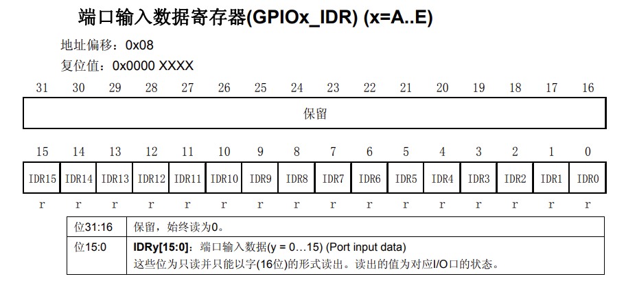
Port Input Data Register
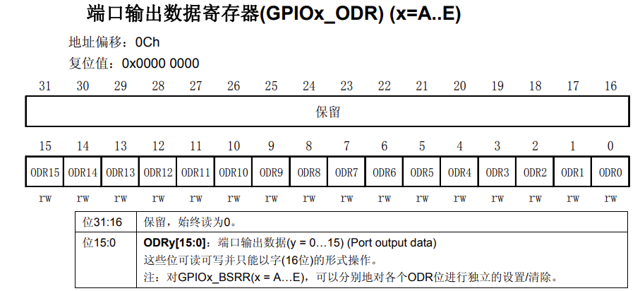
Port Output Data Register
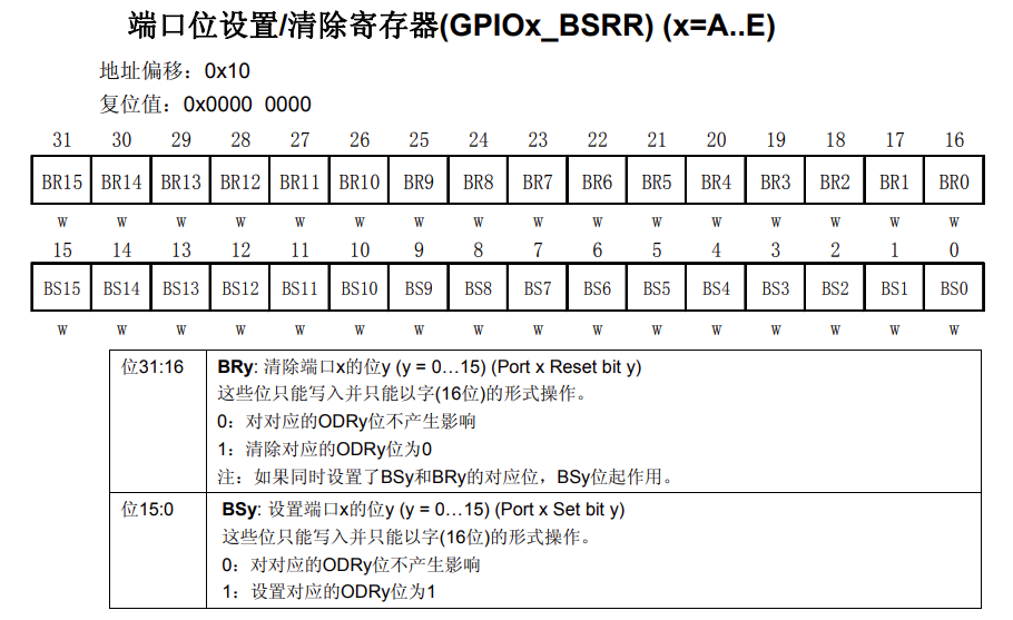
Port Bit Set/Clear Register
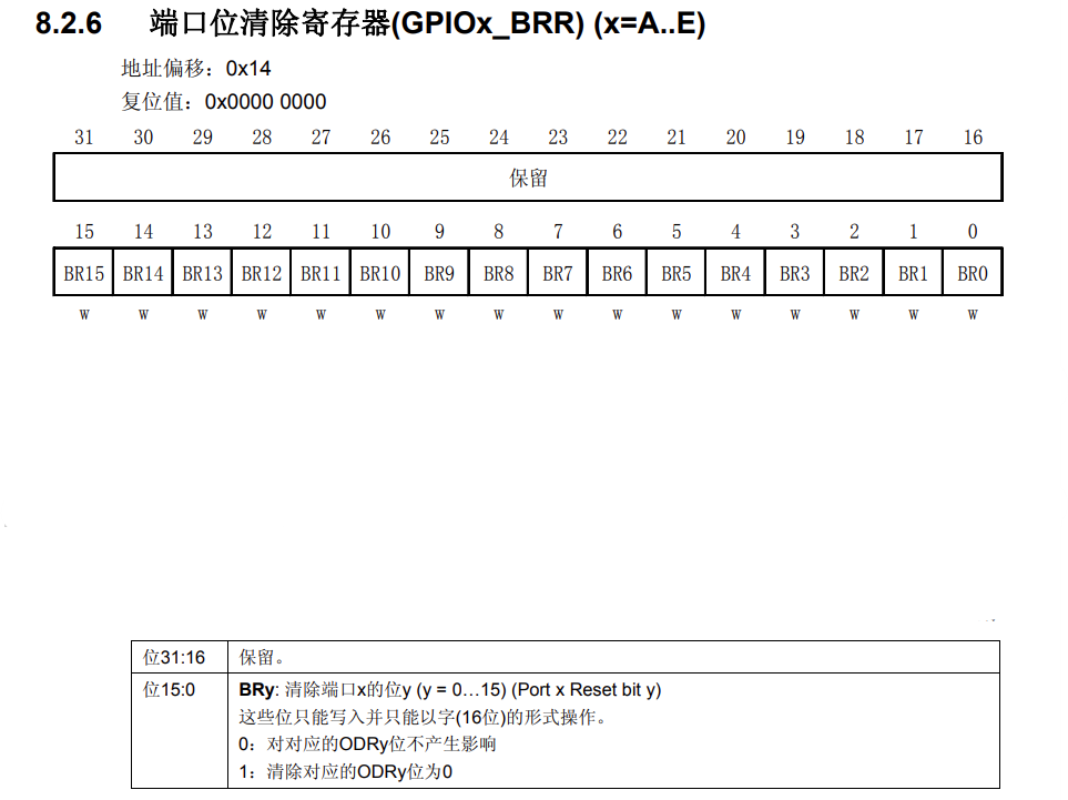
Port Bit Clear Register
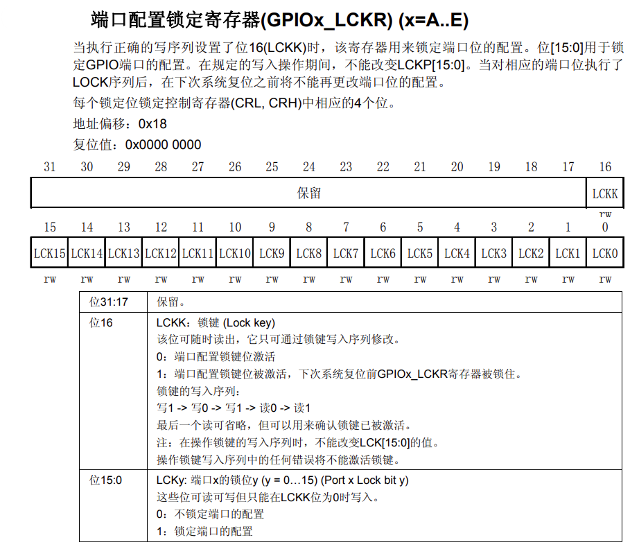
Port Configuration Lock Register


Click Read Original to purchase the OriginCar smart robot kit.