Click the blue text to follow us
0 Preface:
Previously, we learned about STM32CubeIDE and provided the official download link for STM32CubeIDE. This time, we will share the basic configuration required for STM32 projects in STM32CubeIDE, including the configuration of the UART peripheral.
1. Download link for STM32CubeIDE:
https://www.st.com/zh/development-tools/stm32cubeide.html
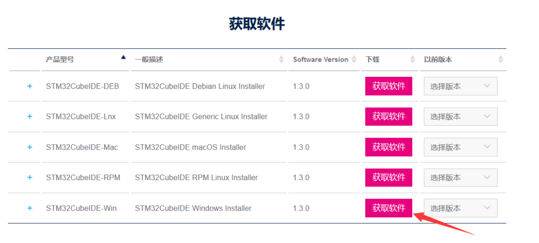
Note: The image indicates a Windows environment; remember that the installation path must not contain Chinese characters.
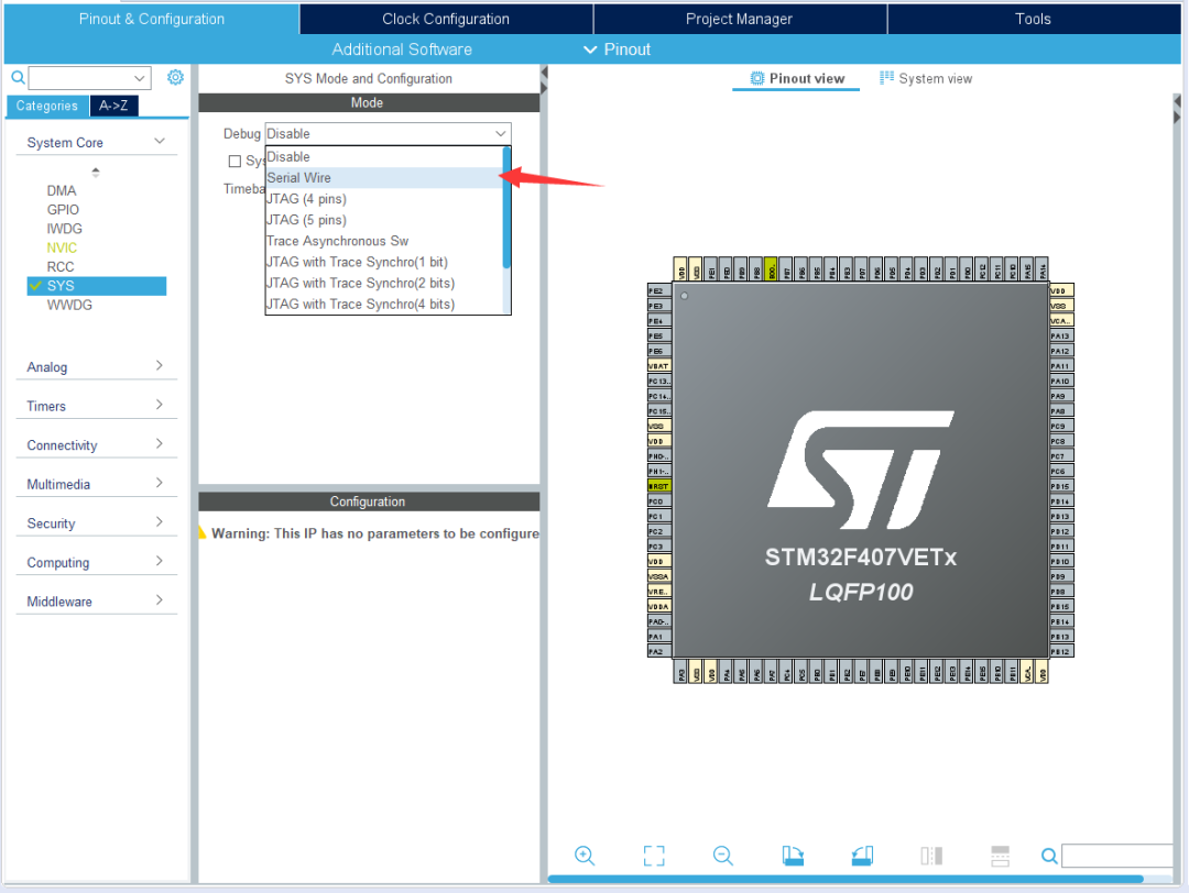
The clock tree configuration of STM32CubeIDE is basically the same as that of Cubemx. Below, we take STM32F407VET6 as an example; the configuration process for other models is generally similar.
1.) Select the download mode, and the pins PA13 (SWDIO) and PA14 (SWCLK) will appear, corresponding to DIO and CLK connected to the downloader; remember the power VCC and GND.
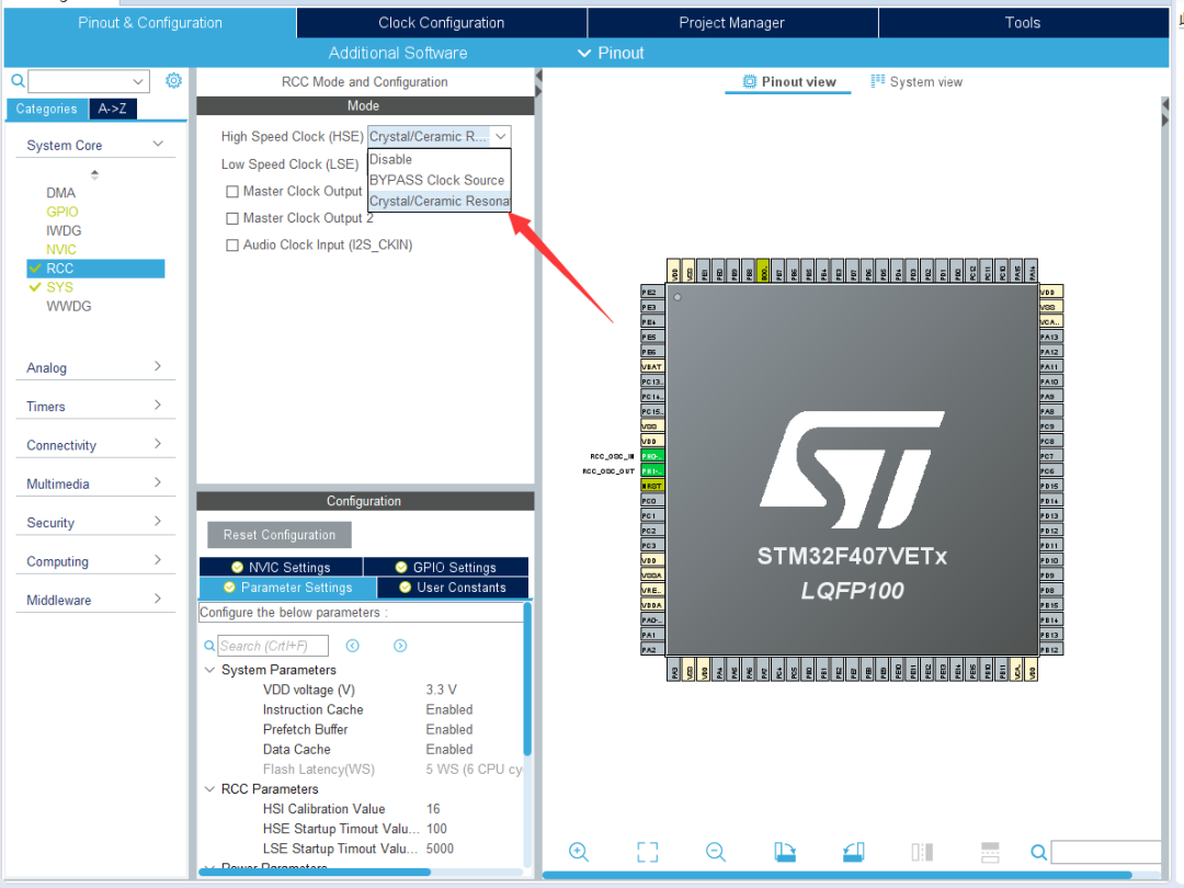
2.) Choose to use an external high-speed crystal oscillator since the RTC clock is not needed for now, so we only configure the use of an external high-speed crystal oscillator.
(The board I am using is a passive crystal, so I chose an external high-speed passive crystal here.)
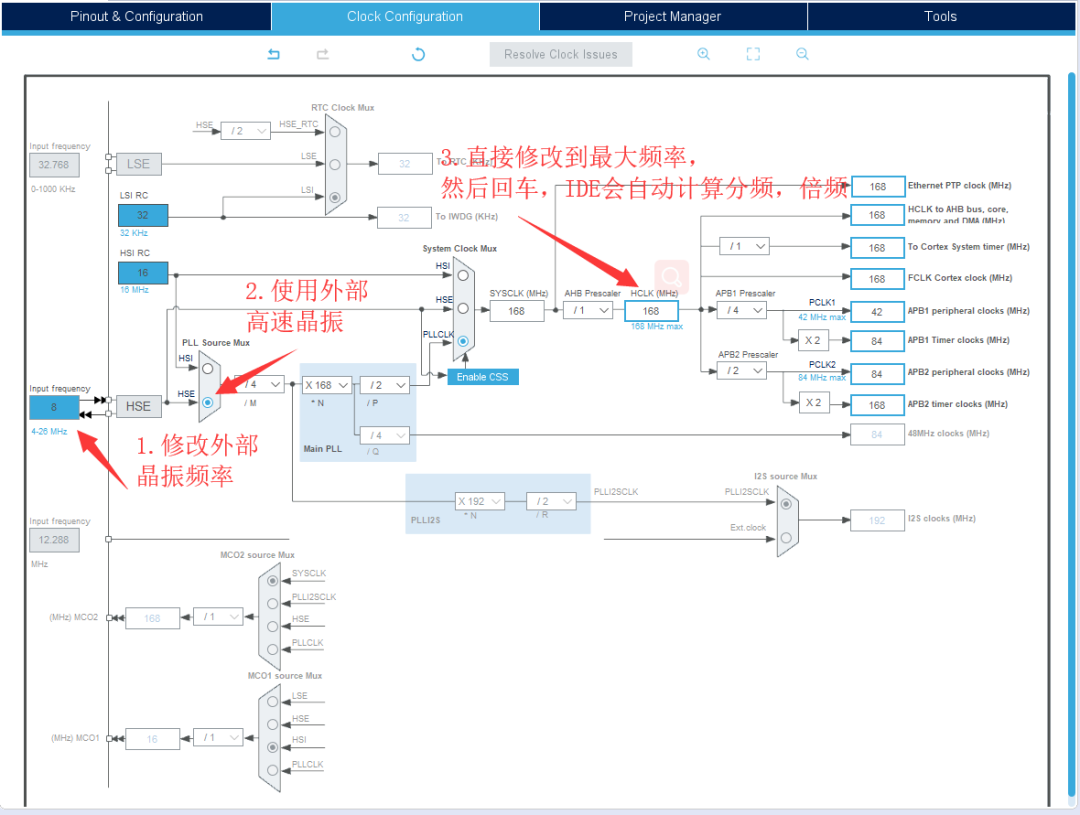
3.) Configure the system clock by selecting Clock Configuration; you can check the frequency of the external crystal on your board before proceeding with the clock tree configuration.
(Here, I used 8M).
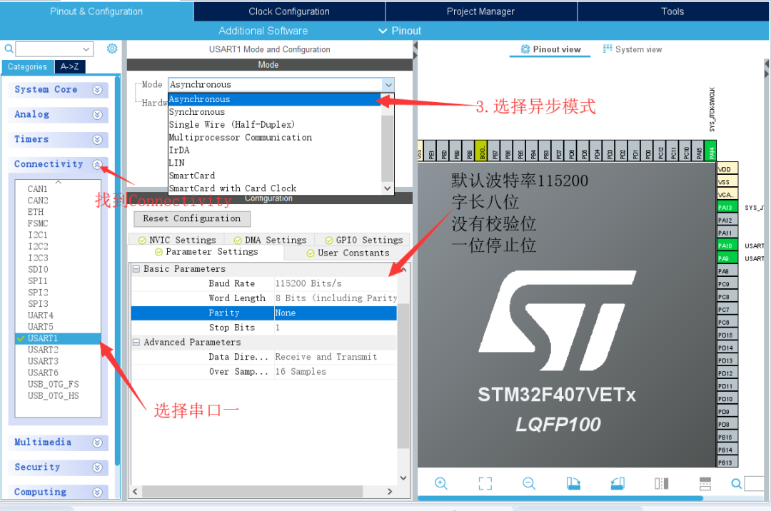
3. Peripheral Configuration
To begin with: Configure UART1, which is mainly used for debugging code and returning parameters. It will be useful later, so let’s first look at configuring UART1.
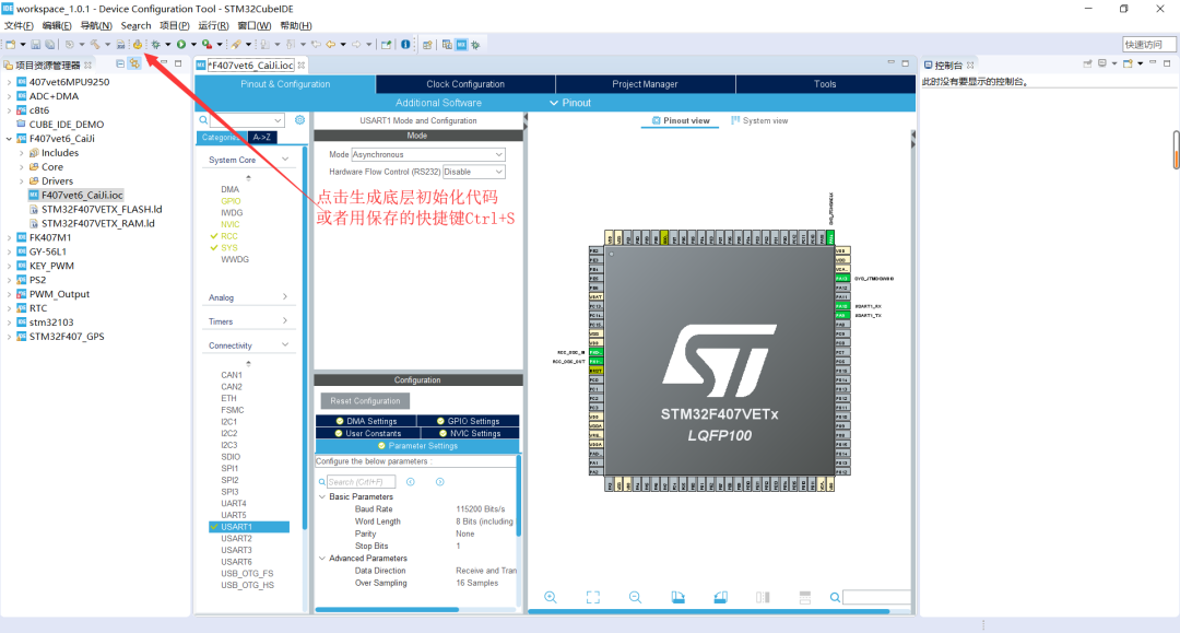
4. Generate Basic Code:
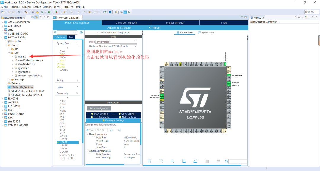
5. Overview of main.c
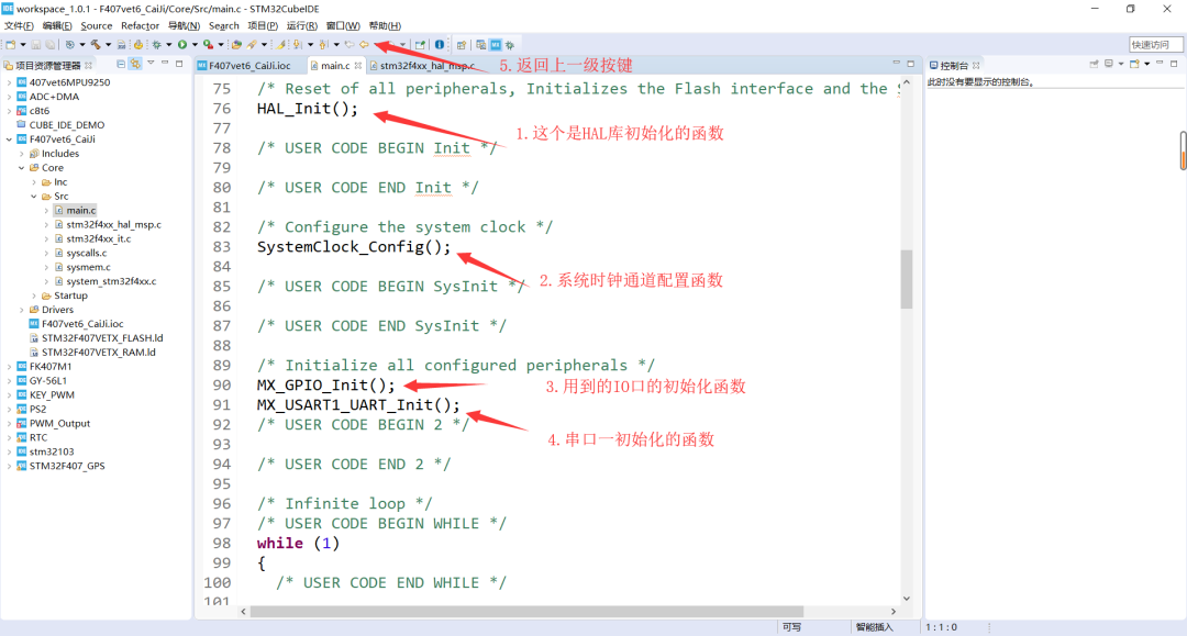
1.) The basic initialization code has been generated above. Locate main.c to check if the configured UART is functioning correctly.
2.) Locate the mai.c file; you will see several initialization functions. If you want to view the initialization code, hold down Ctrl and click the corresponding function name to automatically jump to the function definition. To return, click the back button on the interface.
6. Introduction to UART Send and Receive Functions:
You can see many comments /* USER CODE BEGIN …… */
/* USER CODE END …… */
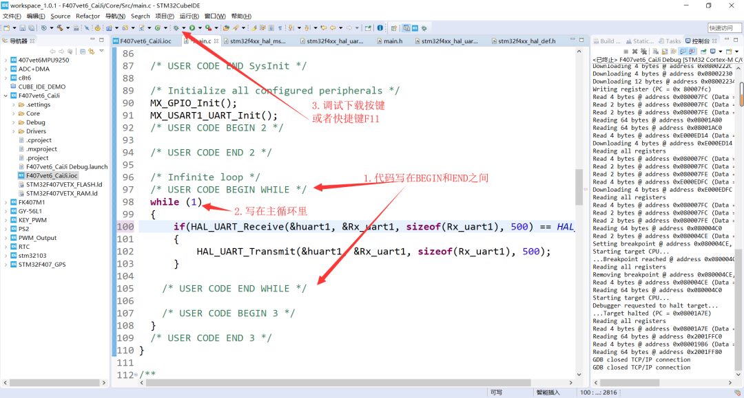
Between BEGIN and END is the area where users can program, and the ellipsis represents the functionality of this area corresponding to the function.
First, define an unsigned, 8-bit integer variable: uint8_t Rx_uart1; under /* USER CODE BEGIN 1 */ in the main function, which will be used to receive data sent from the computer during the experiment.
If the code is not written in the given area, it will be overwritten during the next peripheral initialization, so to avoid unnecessary work, remember to write it in the corresponding position.
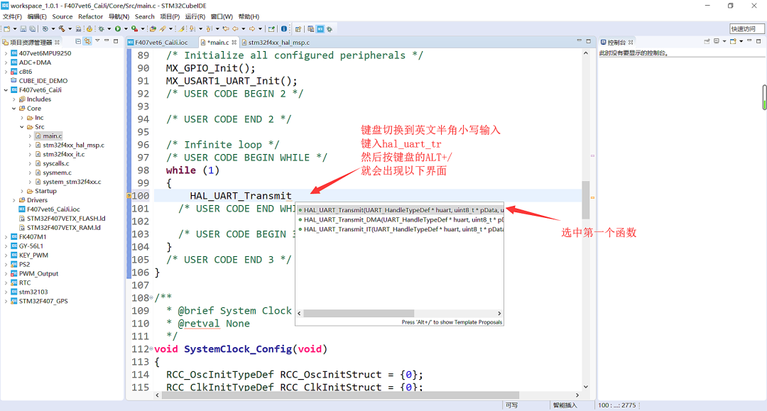
You will obtain the H function -> HAL_UART_Transmit(huart, pData, Size, Timeout)
Note: HAL_UART_Receive(huart, pData, Size, Timeout) is the UART receive function.
The usage is the same. (This function has specific API from the STM32HAL library; once you are familiar with it, you can use the functions in conjunction with the API and the manual.)
1.) HAL_StatusTypeDef: is the function return handle, defining different status values, where HAL_OK
is 0; we can use the return value to determine if sending or receiving was successful.
2.) huart: is the structure pointer, which contains all resources that may be used in UART in various modes.
We do not need to modify it; all settings are done in the graphical interface.
Change to &huart1
3.) pData: data pointer; the address for receiving or sending data should be written here.
Change to &Rx_uart1.
4.) Size: the amount of data to be received or sent, counted in Bytes.
You can write sizeof(Rx_uart1) or 1.
5.) Timeout: the maximum waiting time for each receiving or sending operation.
In this experiment, it will not have an impact.
Change to 500.
7. Writing Code:
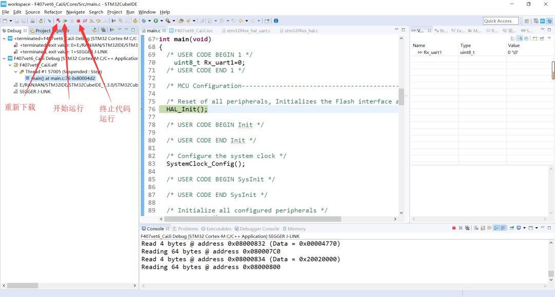
There may be errors with the downloader during the download process; you can change the downloader:
Select Run -> Debug configurations…… a window will pop up; adjust it to the downloader you are using.
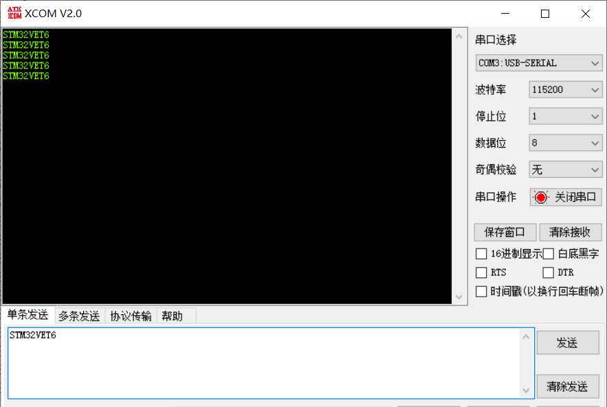
After selecting the downloader, proceed to Debug; after downloading is complete, enter the debugging interface, run directly (shortcut key F8), and open the serial assistant to send characters, which will also be returned (as shown below). Exit debugging (stop running) with Ctrl+F2.

Thus, the process of developing with STM32 using STM32CubeIDE has been completed.
If you have any suggestions or questions, please leave a comment below, or you can join the embedded learning QQ group: 1093852264; we will reply as soon as we see it.
8. Conclusion:
This is a simple process for developing with STM32. Regardless of the model, you need to configure the download mode and clock tree, and then configure according to the different peripherals you are using. When I installed STM32IDE, it initially got stuck on the installation screen due to my computer’s system. After reinstalling the system, I didn’t notice that the installation path contained Chinese characters, which caused a blockage once; finally, changing to an English path allowed for smooth installation. At first, I was not familiar with the icons, but later, as I used it more, I gradually learned where to find things. I hope everyone does not get stuck due to installation path issues. We will also launch a series of articles around the theme project to learn embedded systems together.

Share with your friends!
Join the embedded learning QQ group: 1093852264
A place for collective learning!!!