Introduction
The STM32F103C8T6 microcontroller core board circuit, ADXL345 sensor circuit, heart rate sensor circuit, temperature sensor, and LCD1602 circuit are combined. The ADXL345 gravity acceleration sensor detects the state of a person, calculating the number of steps walked, walking distance, and average speed.
The heart rate sensor detects heart rate in real-time, while the temperature sensor measures temperature. The LCD1602 displays the number of steps, distance, average speed, heart rate, and temperature values in real-time.
Mainly learning about ADXL345, heart rate sensors, etc.
Design Background and Significance
The pedometer is a popular daily exercise progress monitor that can motivate people to challenge themselves, enhance physical fitness, and aid in weight loss.
Early designs used weighted mechanical switches to detect steps, accompanied by a simple counter. When these devices were shaken, a metal ball could be heard sliding back and forth, or a pendulum swinging left and right hitting a block.
The main components of an electronic pedometer are a vibration sensor and an electronic counter. When walking, a person’s center of gravity moves up and down. The up and down displacement at the waist is the most pronounced, making it most suitable for the pedometer to hang on the belt.
The so-called vibration sensor is actually a balance hammer that, when vibrating up and down, breaks the balance, allowing a contact point to switch on/off. The electronic counter completes the main recording and display functions, while other functions, such as calorie consumption and distance conversion, are handled by the circuit.
A common accelerometer is used in pedometers to sense external vibrations. The principle of a commonly used accelerometer is as follows: a small magnet is sealed in a plastic tube, with a coil wrapped around the outside. When the plastic tube moves, the magnet moves in the opposite direction due to inertia, cutting through the coil, generating current in the coil due to electromagnetic induction. The up and down acceleration of the human body approximates a sine wave process, and the output current of the coil is also a sine wave. By measuring the frequency of the sine wave, the number of steps can be derived, which can then be used to calculate distance.
Heart rate is a professional term used to describe the heartbeat cycle, specifically the number of times the heart beats per minute, based on the first sound. In modern Chinese, heart rate is explained as the “frequency of heartbeats.”
Frequency refers to the number of times something occurs in a unit of time. Combining both explanations means the number of times the heart beats within a certain time, indicating the speed of the heartbeat.
The heart rate of a healthy adult ranges from 60 to 100 beats per minute, mostly between 60 and 80 beats per minute, with women generally being slightly faster; children under three often exceed 100 beats per minute; the elderly tend to have slower rates.
An adult’s heart rate exceeding 100 beats per minute (generally not exceeding 160 beats per minute) or infants exceeding 150 beats per minute is termed sinus tachycardia. This is commonly seen in normal individuals during exercise, excitement, agitation, smoking, drinking alcohol, and consuming strong tea. It can also be seen in fever, shock, anemia, hyperthyroidism, heart failure, and the use of atropine, adrenaline, and ephedrine.
If the heart rate is between 160 and 220 beats per minute, it is often referred to as paroxysmal tachycardia. A heart rate below 60 beats per minute (generally above 40 beats per minute) is termed sinus bradycardia.
This can be seen in those engaged in long-term heavy physical labor and athletes; pathologically, it can occur in hypothyroidism, increased intracranial pressure, obstructive jaundice, as well as in cases of overdose or poisoning from digoxin, quinidine, or beta-blockers.
If the heart rate is below 40 beats per minute, it should be considered that there may be atrioventricular conduction block.
Design and Validation of the Scheme
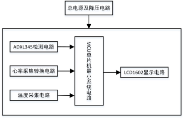
Consists of STM32F103C8T6 microcontroller core board circuit + ADXL345 sensor circuit + heart rate sensor circuit + temperature sensor + LCD1602 circuit.
Control Method
The STM32 microcontroller, part of the STM32 series processors, is a 32-bit microcontroller based on the ARM 7 architecture produced by STMicroelectronics, supporting real-time simulation and tracking.
Using ARM’s latest advanced architecture Cortex-M3 core, it possesses excellent real-time performance, outstanding power consumption control, remarkable and innovative peripherals, and maximum integration, making it very easy to develop and enabling products to quickly enter the market.
Display Scheme
LCD liquid crystal display, driven by the microcontroller, is mainly used to display large amounts of data, text, and graphics. It can display many digits clearly, diversely, and beautifully. Additionally, the programming for the LCD display is simple, inexpensive, and has low power consumption, long lifespan, and strong anti-interference capability.
Inclination Sensor
Using the ADXL345 module based on ADI’s inclination sensor to detect the position information of the elderly, the ADXL345 has powerful functions, with many built-in registers, low cost, and easy control.
Heart Rate Monitoring Module Selection
Using an infrared module to collect heart rate signals, the infrared module has strong anti-interference capability for the collected heart rate signals, and the measured heart rate waveform is relatively stable, making it an ideal choice for design.
Hardware Circuit Design
System Function Analysis
1. Detect the person’s state through the ADXL345 gravity acceleration sensor, calculating the number of steps walked, walking distance, and average speed.
2. Real-time detection of heart rate through the heart rate sensor and temperature measurement through the temperature sensor.
3. The LCD1602 displays the number of steps, distance, average speed, heart rate, and temperature values in real-time.
Overall Structure of the System
Module Circuit Design
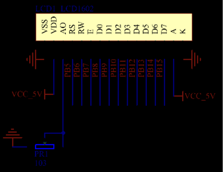
LCD1602 Liquid Crystal Display Module Circuit Design
The LCD display comes in two types: field display and character display. The field display is similar to LED displays; as long as the corresponding signals are sent to the respective pins, they can be displayed. Character display is based on the need to display basic characters. This design uses character-type display.
The system uses the LCD1602 as the display device to output information. Compared to traditional LED display devices, the LCD display module has advantages such as small size, low power consumption, and rich display content, and does not require an additional driver circuit. The LCD display module is now the most commonly used display device in microcontroller application designs. The LCD1602 can display 2 rows of 16 Chinese characters.
Main Technical Parameters of LCD1602
(1) Display capacity is 16×2 characters;
(2) Chip operating voltage is 4.5~5.5V;
(3) Operating current is 2.0mA (5.0V);
(4) The optimal working voltage of the module is 5.0V;
(5) Character size is 2.95×4.35 (W×H) mm.
LCD1602 uses a standard 14-pin interface, with the following pin descriptions
(1) Pin 1: VSS is the ground power supply.
(2) Pin 2: VDD connects to 5V positive power supply.
(3) Pin 3: V0 is the contrast adjustment terminal of the LCD display.
(4) Pin 4: RS is the register selection; when high, it selects the data register, and when low, it selects the instruction register.
(5) Pin 5: RW is the read/write signal line; when high, it performs read operations, and when low, it performs write operations. When both RS and RW are low, instructions or display addresses can be written. When RS is low and RW is high, busy signals can be read; when RS is high and RW is low, data can be written.
(6) Pin 6: E is the enable pin; when E changes from high to low, the LCD module executes the command.
(7) Pins 7-14: D0-D7 are 8-bit bidirectional data lines.
(8) Pins 15-16: empty pins
Control Instruction Description
The LCD1602 liquid crystal module has a total of 11 control instructions in its internal controller.
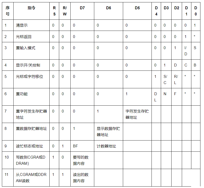
The read and write operations of the 1602 liquid crystal module, as well as the operations of the screen and cursor, are accomplished through instruction programming. (Note: 1 is high level, 0 is low level)
(1) Instruction 1: Clear display, instruction code 01H, cursor reset to address 00H position
(2) Instruction 2: Cursor reset, cursor returns to address 00H
(3) Instruction 3: Cursor and display mode setting I/D: cursor movement direction, high level moves to the right, low level moves to the left S: whether all text on the screen moves to the left or right. High level means effective, low level means ineffective.
(4) Instruction 4: Display on/off control. D: controls whether the overall display is on or off; high level means display is on, low level means display is off. C: controls whether the cursor is on or off; high level means cursor is present, low level means cursor is absent. B: controls whether the cursor blinks; high level means it blinks, low level means it does not blink.
(5) Instruction 5: Cursor or display shifting S/C: high level moves the displayed text, low level moves the cursor.
(6) Instruction 6: Function setting command DL: high level means 4-bit bus, low level means 8-bit bus. N: low level means single-line display, high level means double-line display. F: low level means 5×7 dot matrix characters, high level means 5×10 dot matrix characters.
(7) Instruction 7: Character generator RAM address setting
(8) Instruction 8: DDRAM address setting
(9) Instruction 9: Read busy signal and cursor address BF: busy flag bit; high level means busy, indicating that the module cannot receive commands or data; if low level, it indicates not busy.
(10) Instruction 10: Write data
(11) Instruction 11: Read data
The system uses the LCD1602 as the display device to output information. In this circuit, the potentiometer can adjust the contrast of the liquid crystal display, i.e., its clarity.
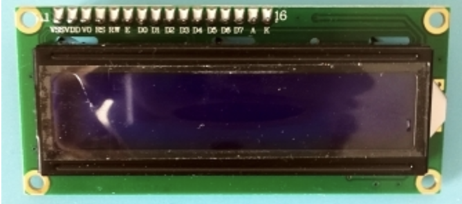
Physical Diagram
ADXL345 Tilt Sensor Module Circuit
Choose the ADXL345 tilt sensor module to detect relevant state information in real-time. The ADXL345 is a small, thin, ultra-low-power 3-axis accelerometer with high resolution (13 bits) and a measurement range of ±16g.
Digital output data is in 16-bit two’s complement format and can be accessed via SPI (3-wire or 4-wire) or I2C digital interfaces.
The ADXL345 is very suitable for mobile device applications.
It can measure static gravity acceleration in tilt detection applications and also measure dynamic acceleration caused by motion or impact.
Its high resolution (3.9mg/LSB) can measure tilt angle changes of less than 1.0°. This device offers various special detection functions.
Activity and inactivity detection functions detect whether movement occurs by comparing acceleration on any axis with user-set thresholds. The tap detection function can detect single and double tap actions in any direction.
The free-fall detection function can detect whether the device is falling. These functions can be independently mapped to one of the two interrupt output pins.
The patented integrated memory management system uses a 32-level FIFO buffer to store data, thereby minimizing the load on the host processor and reducing overall system power consumption.
Low-power mode supports motion-based intelligent power management, allowing threshold sensing and motion acceleration measurement at extremely low power consumption.
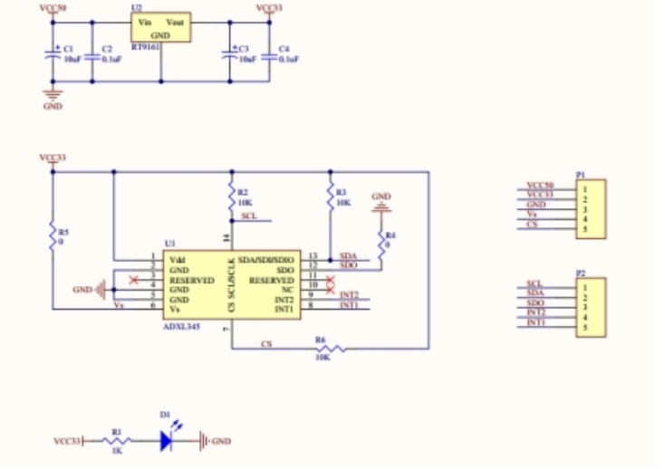
The internal circuit diagram of the ADXL345 module. U2 is the voltage regulator chip, converting 5V DC to 3.3V DC, while C1-C4 are filter capacitors.
R2 and R3 are pull-up resistors to stabilize the signal input. D1 is the power indicator, and R1 is a current-limiting resistor to protect the LED D1.
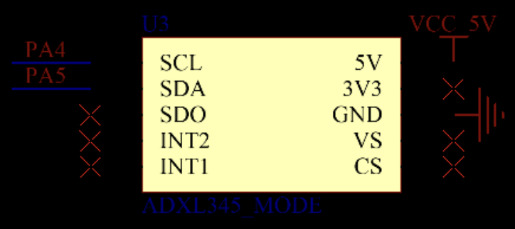
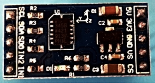
ADXL345 Module
Pulsesensor Heart Rate Sensor Module Circuit Design
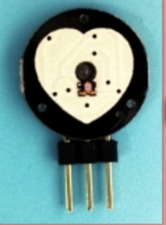
The pulse heart rate sensor is used to test the heartbeat rate, essentially an optical heart rate sensor integrated with amplification and noise cancellation circuits.
This sensor can be used to develop interactive works related to heart rate. It can be worn on a finger or earlobe.
The photoelectric sensor converts the pulse signal into an electrical signal. This device requires the finger to be placed on the sensor’s dial; the photoelectric sensor, which integrates amplification and noise cancellation circuits, emits light from an LED. When the pulse beats, the blood volume in the arteries of the fingertip or earlobe changes periodically, and the intensity of light passing through the fingertip changes simultaneously.
The other side’s phototransistor converts the received infrared light signal into an electrical signal.
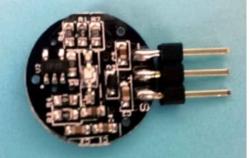
Interface Description
(1) + External 5V
(2) – External GND
(3) S Output Interface (0 and 1)
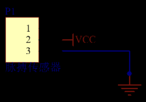
Pulsesensor Heart Rate Sensor Module Interface Schematic
Pulsesensor Heart Rate Sensor Module Physical Diagram
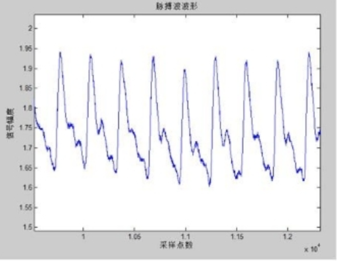
Waveform Output Theoretically from this Pulse Heart Rate Sensor
LM393 Comparator Module Circuit Schematic for Filtering the Pulsesensor Heart Rate Sensor Module
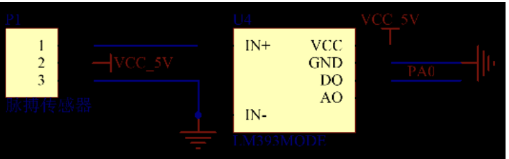
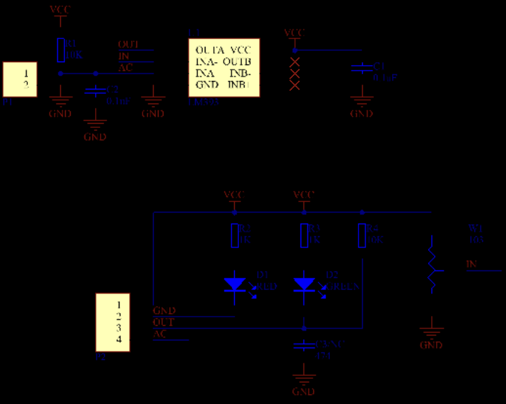
The internal schematic of the LM393 comparator module is shown below.
R1 is the voltage divider resistor, converting the analog information detected by the comparator module into an analog voltage signal. The analog signal is input to the LM393 comparator, which is compared with the analog voltage divided by the potentiometer connected to pin 2 of the LM393 comparator chip, thus deriving a digital signal (i.e., a square wave signal).
C1 and C2 are filter capacitors; C1 filters the power supply to stabilize the output, while C2 filters the analog signal to ensure the stability of the analog signal output. R2 and R3 are current-limiting resistors to protect the LED, preventing it from burning out; the LED is active at a low level.
R4 is a pull-up resistor; pulling up means stabilizing the uncertain signal at a high level through a resistor while also limiting current.
This ensures that the high and low level signals output by the LM393 comparator are more stable when connected to the microcontroller pins.
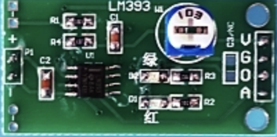
LM393 Comparator Module Physical Diagram
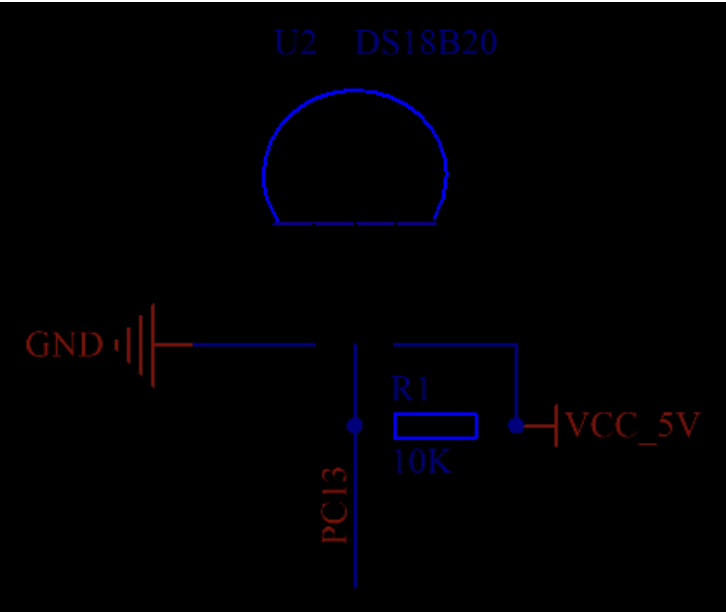
DS18B20 Temperature Sensor Module Circuit
The DS18B20 is a commonly used digital temperature sensor that outputs a digital signal, characterized by small size, low hardware overhead, strong anti-interference capability, and high precision.
The DS18B20 digital temperature sensor is easy to wire and comes in various packaging types, such as pipeline, threaded, magnetically attached, and stainless steel encapsulated, with various models like LTM8877, LTM8874, etc.
Its appearance varies according to the application scenario. The encapsulated DS18B20 can be used in temperature measurement for cable trenches, blast furnace water circulation, boiler temperature measurement, machine room temperature measurement, agricultural greenhouse temperature measurement, clean room temperature measurement, and ammunition depot temperature measurement, among various non-extreme temperature scenarios.
It is wear-resistant, impact-resistant, small in size, easy to use, and comes in various packaging forms, suitable for digital temperature measurement and control in various compact space devices.
Technical Parameters of DS18B20
(1) Unique single-wire interface; when connecting to the microprocessor, only one wire is needed for bidirectional communication between the microprocessor and the DS18B20.
(2) Measurement range: -55℃ to +125℃, inherent temperature measurement error (note, this is not resolution, this was previously incorrect) is 1℃.
(3) Supports multi-point networking; multiple DS18B20s can be connected in parallel on a single wire, with a maximum of 8 in parallel. If too many are connected, the power supply voltage may drop too low, causing unstable signal transmission.
(4) Operating power supply: 3.0~5.5V/DC (can use parasitic power from the data line).
(5) No external components are required during use.
(6) Measurement results are transmitted in 9~12 bit digital format serially.
The DS18B20 temperature sensor has a programmable resolution of 9~12 bits, with the maximum temperature conversion time for 12-bit digital format being 750 milliseconds, and user-defined non-volatile temperature alarm settings. Its application range includes temperature control, industrial systems, consumer electronic thermometers, or any heat-sensitive systems.
Testing has proven that the DS18B20 temperature sensor meets the design requirements.
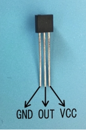
There are generally two packaging types for the DS18B20 temperature sensor, with the same usage. They can be chosen according to the environment of use.
The first type is directly the bare chip, mainly used for air temperature detection. The second type is packaged in a stainless steel tube, waterproof, generally used for water temperature or liquid temperature detection.
Physical diagrams are as follows:
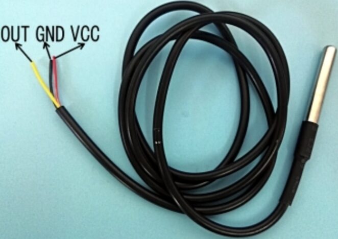
DS18B20 temperature sensor physical diagram (waterproof)
The schematic diagram of the DS18B20 temperature sensor is as follows. A 10K resistor is a pull-up resistor to ensure more stable data reading from the DS18B20 sensor.
Program Flowchart
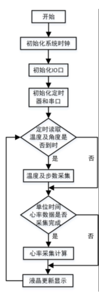
System operation flowchart
Code
main.c
#include "led.h"
#include "delay.h"
#include "sys.h"
#include "usart.h"
#include <stdio.h>
#include "timer.h"
#include "key.h"
#include "exti.h"
#include "adxl345.h"
#include "lcd1602.h"
#include "ds18b20.h"

unsigned char ReadAdxl345;       //定时读取adxl345数据
unsigned char ErrorNum=0;   //记录错误次数
unsigned char CheckNum=0;   //检测次数
char dis0[16];//液晶数组显示暂存
char dis1[35];
unsigned int xlTab[5];//心率数组
unsigned char count=0;    //心率滤波计数
unsigned int xinLater=0;//    心率延时处理
unsigned int xinLv =0;    //心率值
unsigned int BuShu=0;//步数
unsigned int Normal_num=0;            //正常次数
unsigned int Error_num=0;            //倾斜次数
unsigned int disBuShu = 0;  //显示步数
float disJuLi = 0;//显示距离
float temperature;  //温度
unsigned char readTemp = 0;    //读取温度标志

int main(void){     delay_init();             //延时函数初始化          uart_init(9600);         //串口初始化为9600  TIM3_Int_Init(49,7199);//50ms          EXTIX_Init();        // 初始化外部中断    LED_Init();                  //初始化与LED连接的硬件接口    KEY_Init();            //初始化按键
    Lcd_GPIO_init();  //初始化lcd引脚    Lcd_Init();          //初始化lcd屏幕    delay_ms(200);
  Init_ADXL345();  if(Single_Read_ADXL345(0X00)==0xe5)      {    delay_ms(5);  }  else  {    delay_ms(3);  }
    while(1)    {
    if(ReadAdxl345== 1)   //定时读取adxl345数据    {      ReadAdxl345= 0;      ReadData_x();                          //三轴检测函数      CheckNum++;      if((temp_Y>450)||(temp_Y<-450)) //查看正常次数           {        Normal_num++;  //正常次数++      }      else      {        Error_num++;//倾斜次数      }      if((Error_num!=0)&&&(Normal_num!=0))//检测到步数      {                BuShu++;   //步数脉冲量++        Error_num=0;    //清除一个周期检测        Normal_num=0;      }    }
        if(disFlag==1)       //显示标志        {            disFlag = 0;
            readTemp++;  //定时计数            if(readTemp >= 8)//约800ms处理一次数据 温度            {                readTemp =0;//重新计数                temperature=(float)DS18B20_Get_Temp()/10;    //缩小10倍为实际值                        }
            disBuShu = BuShu/2;  //显示步数            disJuLi = disBuShu*0.45;//显示距离
            sprintf(dis0,"X:%03d/min %4.1f C",xinLv,temperature);//打印            Lcd_Puts(0,0,(unsigned char *)dis0);    //显示            Lcd_1Put(14,0,0xdf);//显示符号            sprintf(dis1,"BS:%03d JL:%4.1fm  ",disBuShu,disJuLi);//打印            Lcd_Puts(0,1,(unsigned char *)dis1);    //显示
        }        }                                                }
adxl345.c
#include "stm32f10x.h"
#include "delay.h"
#include "adxl345.h"

#define SDA_RCC            RCC_APB2Periph_GPIOA
#define SDA_GPIO        GPIOA
#define SDA_GPIO_PIN    GPIO_Pin_5
#define SCL_RCC            RCC_APB2Periph_GPIOA
#define SCL_GPIO        GPIOA
#define SCL_GPIO_PIN    GPIO_Pin_4
#define SCL_OUT() SCL_Set_Output() //置位scl
#define SET_SCL() GPIO_SetBits(SCL_GPIO, SCL_GPIO_PIN) //置位scl
#define CLE_SCL() GPIO_ResetBits(SCL_GPIO, SCL_GPIO_PIN)//清楚scl
#define SDA_OUT() SDA_Set_Output()
#define SDA_INT() SDA_Set_Input()
#define SET_SDA() GPIO_SetBits(SDA_GPIO, SDA_GPIO_PIN)//置位sda
#define CLE_SDA() GPIO_ResetBits(SDA_GPIO, SDA_GPIO_PIN)//清楚sda
#define SDA_VAL() GPIO_ReadInputDataBit(SDA_GPIO, SDA_GPIO_PIN)
#define    SlaveAddress   0xA6      //定义器件在IIC总线中的从地址,根据ALT  ADDRESS地址引脚不同修改                  //ALT  ADDRESS引脚接地时地址为0xA6,接电源时地址为0x3A
unsigned char BUF[8];                         //接收数据缓存区          unsigned char ge,shi,bai,qian,wan;           //显示变量
unsigned char err;float temp_X,temp_Y,temp_Z;

void SCL_Set_Output(void){    GPIO_InitTypeDef  GPIO_InitStructure;    GPIO_InitStructure.GPIO_Pin = SCL_GPIO_PIN;                     GPIO_InitStructure.GPIO_Mode = GPIO_Mode_Out_PP;              GPIO_InitStructure.GPIO_Speed = GPIO_Speed_50MHz;             GPIO_Init(SCL_GPIO, &GPIO_InitStructure);                                         }
void SDA_Set_Output(void){    GPIO_InitTypeDef  GPIO_InitStructure;    GPIO_InitStructure.GPIO_Pin = SDA_GPIO_PIN;                     GPIO_InitStructure.GPIO_Mode = GPIO_Mode_Out_PP;              GPIO_InitStructure.GPIO_Speed = GPIO_Speed_50MHz;             GPIO_Init(SDA_GPIO, &GPIO_InitStructure);                                         }
void SDA_Set_Input(void){    GPIO_InitTypeDef  GPIO_InitStructure;    GPIO_InitStructure.GPIO_Pin = SDA_GPIO_PIN;                     GPIO_InitStructure.GPIO_Mode = GPIO_Mode_IPU;              GPIO_InitStructure.GPIO_Speed = GPIO_Speed_50MHz;             GPIO_Init(SDA_GPIO, &GPIO_InitStructure);                     }
/**************************************起始信号**************************************/
void ADXL345_Start(void){    SCL_OUT();    SDA_OUT();    SET_SDA();//SDA = 1;                    //拉高数据线    SET_SCL();//SCL = 1;                    //拉高时钟线    delay_us(2);//Delay5us();                 //延时    CLE_SDA();//SDA = 0;                    //产生下降沿    delay_us(2);//Delay5us();                 //延时    CLE_SCL();//SCL = 0;                    //拉低时钟线}
/**************************************停止信号**************************************/
void ADXL345_Stop(void){    SCL_OUT();    SDA_OUT();    CLE_SDA();//SDA = 0;                    //拉低数据线    SET_SCL();//SCL = 1;                    //拉高时钟线    delay_us(2);//Delay5us();                 //延时    SET_SDA();//SDA = 1;                    //产生上升沿    delay_us(2);//Delay5us();                 //延时    CLE_SCL();}
/**************************************发送应答信号入口参数:ack (0:ACK 1:NAK)**************************************/
void ADXL345_SendACK(uchar ack){       SCL_OUT();    SDA_OUT();    if(ack==0)//SDA = ack;                  //写应答信号    {      CLE_SDA();    }    else    {      SET_SDA();    }    SET_SCL();//SCL = 1;                    //拉高时钟线    delay_us(2);//Delay5us();                 //延时    CLE_SCL();//SCL = 0;                    //拉低时钟线    delay_us(5);//Delay5us();                 //延时}
/**************************************接收应答信号**************************************/
uchar ADXL345_RecvACK(void){    SDA_INT();    SCL_OUT();    SET_SCL();//SCL = 1;                    //拉高时钟线    delay_us(2);//    Delay5us();                 //延时    SET_SCL();    if(SDA_VAL()== Bit_SET)   //CY = SDA;                   //读应答信号    {      err = 1;    }    else    {      err = 0;    }
    CLE_SCL() ;//SCL = 0;                    //拉低时钟线    delay_us(5);//    Delay5us();                 //延时    SDA_OUT();    return err;}
/**************************************向IIC总线发送一个字节数据**************************************/
void ADXL345_SendByte(unsigned char dat){    unsigned char i;    SCL_OUT();    SDA_OUT();    for (i=0; i<8; i++)         //8位计数器    {        delay_us(5);             //延时        if(dat&0x80)  //SDA = CY;               //送数据口        {SET_SDA();}        else        {CLE_SDA();}               delay_us(5);             //延时        SET_SCL();//SCL = 1;                //拉高时钟线        delay_us(5);             //延时        CLE_SCL();//SCL = 0;                //拉低时钟线        dat <<= 1;              //移出数据的最高位    }    ADXL345_RecvACK();}
/**************************************从IIC总线接收一个字节数据**************************************/
unsigned char ADXL345_RecvByte(void){    unsigned char i;    unsigned char Mid;    unsigned char dat = 0;    SDA_INT();    SCL_OUT();
    for (i=0; i<8; i++)         //8位计数器    {        dat <<= 1;        delay_us(5);            //延时        SET_SCL();
            if(SDA_VAL()== Bit_SET)   //CY = SDA;                   //读应答信号            {                Mid = 1;            }            else            {                Mid = 0;            }
//        Mid=SDA_VAL();        if(Mid) dat++;        delay_us(5);             CLE_SCL();//SCL = 0;                //拉低时钟线    }    return dat;}
//******单字节写入*******************************************
void Single_Write_ADXL345(uchar REG_Address,uchar REG_data){    ADXL345_Start();                  //起始信号    ADXL345_SendByte(SlaveAddress);   //发送设备地址+写信号    ADXL345_SendByte(REG_Address);    //内部寄存器地址,请参考中文pdf22页     ADXL345_SendByte(REG_data);       //内部寄存器数据,请参考中文pdf22页     ADXL345_Stop();                   //发送停止信号}
//********单字节读取*****************************************uchar Single_Read_ADXL345(uchar REG_Address){  uchar REG_data;    ADXL345_Start();                          //起始信号    ADXL345_SendByte(SlaveAddress);           //发送设备地址+写信号    ADXL345_SendByte(REG_Address);            //发送存储单元地址,从0开始        ADXL345_Start();                          //起始信号    ADXL345_SendByte(SlaveAddress+1);         //发送设备地址+读信号    REG_data=ADXL345_RecvByte();              //读出寄存器数据    ADXL345_SendACK(1);       ADXL345_Stop();                           //停止信号    return REG_data; }
//*********************************************************////连续读出ADXL345内部加速度数据,地址范围0x32~0x37////*********************************************************void Multiple_Read_ADXL345(void){   uchar i;    ADXL345_Start();                          //起始信号    ADXL345_SendByte(SlaveAddress);           //发送设备地址+写信号    ADXL345_SendByte(0x32);                   //发送存储单元地址,从0x32开始        ADXL345_Start();                          //起始信号    ADXL345_SendByte(SlaveAddress+1);         //发送设备地址+读信号     for (i=0; i<6; i++)                      //连续读取6个地址数据,存储中BUF    {        BUF[i] = ADXL345_RecvByte();          //BUF[0]存储0x32地址中的数据        if (i == 5)        {           ADXL345_SendACK(1);                //最后一个数据需要回NOACK        }        else        {          ADXL345_SendACK(0);                //回应ACK       }   }    ADXL345_Stop();                          //停止信号    delay_ms(5);}
//*****************************************************************
//初始化ADXL345,根据需要请参考pdf进行修改************************
void Init_ADXL345(void){   Single_Write_ADXL345(0x31,0x0B);   //测量范围,正负16g,13位模式   Single_Write_ADXL345(0x2C,0x08);   //速率设定为12.5 参考pdf13页   Single_Write_ADXL345(0x2D,0x08);   //选择电源模式   参考pdf24页   Single_Write_ADXL345(0x2E,0x80);   //使能 DATA_READY 中断   Single_Write_ADXL345(0x1E,0x00);   //X 偏移量 根据测试传感器的状态写入pdf29页   Single_Write_ADXL345(0x1F,0x00);   //Y 偏移量 根据测试传感器的状态写入pdf29页   Single_Write_ADXL345(0x20,0x05);   //Z 偏移量 根据测试传感器的状态写入pdf29页}
//***********************************************************************//显示x轴void ReadData_x(void){     int  dis_data;                       //变量  Multiple_Read_ADXL345();           //连续读出数据,存储在BUF中  dis_data=(BUF[1]<<8)+BUF[0];  //合成数据   //  if(dis_data<0)//  {//    dis_data=-dis_data;//  }  temp_X=(float)dis_data*3.9;  //计算数据和显示,查考ADXL345快速入门第4页  dis_data=(BUF[3]<<8)+BUF[2];  //合成数据   //  if(dis_data<0)//  {//    dis_data=-dis_data;//  }  temp_Y=(float)dis_data*3.9;  //计算数据和显示,查考ADXL345快速入门第4页  dis_data=(BUF[5]<<8)+BUF[4];    //合成数据   //  if(dis_data<0)//  {//    dis_data=-dis_data;//  }  temp_Z=(float)dis_data*3.9;  //计算数据和显示,查考ADXL345快速入门第4页}
adxl345.h
#define uint unsigned int
#define uchar unsigned char

extern float temp_X,temp_Y,temp_Z;

void SCL_Set_Output(void);
void SDA_Set_Output(void);
void SDA_Set_Input(void);
void Init_ADXL345(void);
void  Single_Write_ADXL345(uchar REG_Address,uchar REG_data);   //??????
uchar Single_Read_ADXL345(uchar REG_Address);                   //???????????
void  Multiple_Read_ADXL345(void);                                  //????????????
void ADXL345_Start(void);
void ADXL345_Stop(void);
void ADXL345_SendACK(uchar ack);
uchar  ADXL345_RecvACK(void);
void ADXL345_SendByte(uchar dat);
uchar ADXL345_RecvByte(void);
void ADXL345_ReadPage(void);
void ADXL345_WritePage(void);
void ReadData_x(void);
ds18b20.c
#include "ds18b20.h"
#include "delay.h"
//IO方向设置//#define DS18B20_IO_IN()  {GPIOA->CRL&=0XFFFFFFF0;GPIOA->CRL|=8<<0;}//#define DS18B20_IO_OUT() {GPIOA->CRL&=0XFFFFFFF0;GPIOA->CRL|=3<<0;}
void DS18B20_IO_IN(void){    GPIO_InitTypeDef GPIO_InitStructure;
     RCC_APB2PeriphClockCmd(RCC_GPIO_DQ,ENABLE);//使能PORTA,PORTC时钟
    GPIO_InitStructure.GPIO_Pin  = GPIO_DQ_PIN;    GPIO_InitStructure.GPIO_Mode = GPIO_Mode_IPU; //设置成上拉输入     GPIO_Init(GPIO_DQ, &GPIO_InitStructure);//初始化}
void DS18B20_IO_OUT(void){ GPIO_InitTypeDef  GPIO_InitStructure;
 RCC_APB2PeriphClockCmd(RCC_GPIO_DQ, ENABLE);     //使能
 GPIO_InitStructure.GPIO_Pin = GPIO_DQ_PIN;                  GPIO_InitStructure.GPIO_Mode = GPIO_Mode_Out_PP;          //推挽输出 GPIO_InitStructure.GPIO_Speed = GPIO_Speed_50MHz;         //IO口速度为50MHz GPIO_Init(GPIO_DQ, &GPIO_InitStructure);                     //根据设定参数初始化}//初始化DS18B20的IO口 DQ 同时检测DS的存在//返回1:不存在//返回0:存在         u8 DS18B20_Init(void){     GPIO_InitTypeDef  GPIO_InitStructure;
     RCC_APB2PeriphClockCmd(RCC_GPIO_DQ, ENABLE);     //使能PORTA口时钟
     GPIO_InitStructure.GPIO_Pin = GPIO_DQ_PIN;                //PORTA0 推挽输出     GPIO_InitStructure.GPIO_Mode = GPIO_Mode_Out_PP;                GPIO_InitStructure.GPIO_Speed = GPIO_Speed_50MHz;     GPIO_Init(GPIO_DQ, &GPIO_InitStructure);
     GPIO_SetBits(GPIO_DQ,GPIO_DQ_PIN);    //输出1
    DS18B20_Rst();
    return DS18B20_Check();}
//复位DS18B20void DS18B20_Rst(void)       {                     DS18B20_IO_OUT(); //SET PA0 OUTPUT    DS18B20_DQ_OUT=0; //拉低DQ    delay_us(750);    //拉低750us    DS18B20_DQ_OUT=1; //DQ=1     delay_us(15);     //15US}//等待DS18B20的回应//返回1:未检测到DS18B20的存在//返回0:存在u8 DS18B20_Check(void)        {       u8 retry=0;    DS18B20_IO_IN();//SET PA0 INPUT         while (DS18B20_DQ_IN&&retry<200)    {        retry++;        delay_us(1);    };         if(retry>=200)return 1;    else retry=0;    while (!DS18B20_DQ_IN&&retry<240)    {        retry++;        delay_us(1);    };    if(retry>=240)return 1;            return 0;}//从DS18B20读取一个位//返回值:1/0u8 DS18B20_Read_Bit(void)              // read one bit{    u8 data;    DS18B20_IO_OUT();//SET PA0 OUTPUT    DS18B20_DQ_OUT=0;     delay_us(2);    DS18B20_DQ_OUT=1;     DS18B20_IO_IN();//SET PA0 INPUT    delay_us(12);    if(DS18B20_DQ_IN)data=1;    else data=0;         delay_us(50);               return data;}//从DS18B20读取一个字节//返回值:读到的数据u8 DS18B20_Read_Byte(void)    // read one byte{            u8 i,j,dat;    dat=0;    for (i=1;i<=8;i++)     {        j=DS18B20_Read_Bit();        dat=(j<<7)|(dat>>1);    }                                return dat;}//写一个字节到DS18B20//dat:要写入的字节void DS18B20_Write_Byte(u8 dat)     {                 u8 j;    u8 testb;    DS18B20_IO_OUT();//SET PA0 OUTPUT;    for (j=1;j<<=8;j++)     {        testb=dat&0x01;        dat=dat>>1;        if (testb)         {            DS18B20_DQ_OUT=0;// Write 1            delay_us(2);                                        DS18B20_DQ_OUT=1;            delay_us(60);                     }        else         {            DS18B20_DQ_OUT=0;// Write 0            delay_us(60);                         DS18B20_DQ_OUT=1;            delay_us(2);                                  }    }}//开始温度转换void DS18B20_Start(void)// ds1820 start convert{                                              DS18B20_Rst();           DS18B20_Check();         DS18B20_Write_Byte(0xcc);// skip rom    DS18B20_Write_Byte(0x44);// convert}
//从ds18b20得到温度值//精度:0.1C//返回值:温度值 (-550~1250) short DS18B20_Get_Temp(void){    u8 temp;    u8 TL,TH;    short tem;    DS18B20_Start ();                    // ds1820 start convert    DS18B20_Rst();    DS18B20_Check();         DS18B20_Write_Byte(0xcc);// skip rom    DS18B20_Write_Byte(0xbe);// convert            TL=DS18B20_Read_Byte(); // LSB       TH=DS18B20_Read_Byte(); // MSB
    if(TH>7)    {        TH=~TH;        TL=~TL;         temp=0;//温度为负      }else temp=1;//温度为正                tem=TH; //获得高八位    tem<<=8;        tem+=TL;//获得底八位    tem=(float)tem*0.625;//转换         if(temp)return tem; //返回温度值    else return -tem;    }
ds18b20.h
#ifndef __DS18B20_H
#define __DS18B20_H
#include "sys.h"
#define GPIO_DQ       GPIOC                 //  使能端口组
#define GPIO_DQ_PIN   GPIO_Pin_13            //  使能端口号
#define RCC_GPIO_DQ   RCC_APB2Periph_GPIOC  //  使能时钟组
#define    DS18B20_DQ_OUT PCout(13) //数据端口
#define    DS18B20_DQ_IN  PCin(13)  //数据端口
void DS18B20_IO_IN(void);
void DS18B20_IO_OUT(void);

u8 DS18B20_Init(void);            //初始化DS18B20
short DS18B20_Get_Temp(void);    //获取温度
void DS18B20_Start(void);        //开始温度转换
void DS18B20_Write_Byte(u8 dat);//写入一个字节
u8 DS18B20_Read_Byte(void);        //读出一个字节
u8 DS18B20_Read_Bit(void);        //读出一个位
u8 DS18B20_Check(void);            //检测是否存在DS18B20
void DS18B20_Rst(void);            //复位DS18B20
#endif

↑ Hot Course, Limited Time Coupon! 🎉 Grab it Fast ↑