This section marks the beginning of our project, hardware groundwork. To start this project, I also need to learn about the hardware part, as both are indispensable.This collection is my study of hardware, recording some basics, taking it slow.Now let’s start our project.Here we use a motor to act as a door lock switch (the motor controls the rotation direction, combined with some gears to control the door lock opening and closing), and we will use theL9110S dual-channel DC motor driver chip.I randomly found a manufacturer’s chip online, let’s take a screenshot here,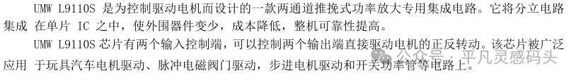
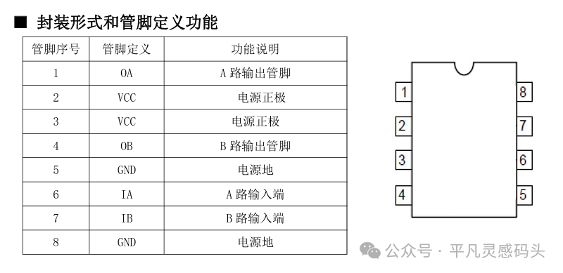 The above is an introduction to this chip and its pin definitions. We mainly look at the two inputs and outputs of this chip. These four pinsInput: The level signal transmitted from the main control chip to this chip to control the motor’s rotation direction.Output: These two pins of the chip connect to our motor to drive it.
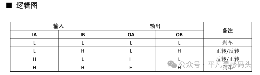 You can see this logic diagram clearly describing the logical relationship of these four pins. Now I know that the two IO ports of the main control chip output high and low levels to control the motor’s rotation, so I need to configure these two IO ports, (here we generally look at the schematic to see which GPIO the two motor ports are connected to) Here we will use PB3 and PB4 as substitutes.Now we can directly configure these two IO ports to control the motor’s rotation, so let’s configure these two IOs.
RCC_APB2PeriphClockCmd(RCC_APB2Periph_GPIOB, ENABLE);GPIO_InitTypeDef GPIO_InitStruct = {0};GPIO_StructInit(&GPIO_InitStruct);GPIO_InitStruct.GPIO_Pin = GPIO_Pin_3 | GPIO_Pin_4;GPIO_InitStruct.GPIO_Mode = GPIO_Mode_OUT;GPIO_InitStruct.GPIO_OType = GPIO_OType_PP;GPIO_Init(GPIOB, &GPIO_InitStruct);Then useGPIO_SetBits() and GPIO_ResetBits() to control the IO ports to output high and low levels.Now let’s create a wrapper function.
void Door_Init(){ GPIO_Init(); GPIO_ResetBits(GPIOB,GPIO_Pin_3|GPIO_Pin_4);}void Door_Open(){ GPIO_SetBits(GPIOB,GPIO_Pin_3); GPIO_ResetBits(GPIOB,GPIO_Pin_4);}void Door_Close(){ GPIO_SetBits(GPIOB,GPIO_Pin_4); GPIO_ResetBits(GPIOB,GPIO_Pin_3);}Are you following along?Now I want to control the speed; I not only want to control the door lock’s opening and closing but also the speed of the door lock’s operation.Two IO ports control the motor’s rotation, butthe L9110S dual-channel DC motor driver chip does not have extra IO ports to connect to a PWM channel. So how do we achieve this?PWM output is a waveform that outputs high and low levels within a specified period, and then we set the duty cycle, which configures the ratio of high and low levels in this waveform.Now let’s think, if I have one IO port at low level and the other at high level to control the motor to turn right,then we can reuse both IO ports as timer channels, setting one IO port’s duty cycle to 0 and the other IO port’s duty cycle to 1~1000. Is the situation the same as above? The answer is:Yes, it is.When we set the high level as the effective level, then the duty cycle of 0 outputs a low level, which matches one of the chip’s input pins. We give it a low level, and then the other pin’s duty cycle is set to 1~1000, which matches the other input pin of the chip being high level and also a PWM waveform. Thus, we can control the motor’s rotation direction and speed through two IOs, thereby controlling the door lock’s opening and closing and the speed of the door lock’s operation.Now we can configure and write the door lock driver code.First, the initialization of the door lock includes GPIO configuration andtimer base unit and output comparison.
void timer2_ch2_pwm(void){ RCC_AHB1PeriphClockCmd(RCC_AHB1Periph_GPIOB,ENABLE); GPIO_InitTypeDef GPIO_InitStruct = {0}; GPIO_InitStruct.GPIO_Mode = GPIO_Mode_AF; GPIO_InitStruct.GPIO_OType = GPIO_OType_PP; GPIO_InitStruct.GPIO_Pin = GPIO_Pin_3; GPIO_InitStruct.GPIO_PuPd = GPIO_PuPd_NOPULL; GPIO_InitStruct.GPIO_Speed = GPIO_Speed_2MHz; GPIO_Init(GPIOB,&GPIO_InitStruct); GPIO_PinAFConfig(GPIOB,GPIO_PinSource3,GPIO_AF_TIM2); RCC_APB1PeriphClockCmd(RCC_APB1Periph_TIM2,ENABLE); TIM_TimeBaseInitTypeDef TIM_TimeBaseInitStruct = {0}; TIM_TimeBaseInitStruct.TIM_CounterMode = TIM_CounterMode_Up; TIM_TimeBaseInitStruct.TIM_Period = 1000 - 1; TIM_TimeBaseInitStruct.TIM_Prescaler = 84 - 1; TIM_TimeBaseInit(TIM2,&TIM_TimeBaseInitStruct); TIM_OCInitTypeDef TIM_OCInitStruct = {0}; TIM_OCInitStruct.TIM_OCMode = TIM_OCMode_PWM1; TIM_OCInitStruct.TIM_OCPolarity = TIM_OCPolarity_High; TIM_OCInitStruct.TIM_OutputState = TIM_OutputState_Enable; TIM_OCInitStruct.TIM_Pulse = 0; TIM_OC2Init(TIM2,&TIM_OCInitStruct); TIM_Cmd(TIM2,ENABLE);}This is a configuration function for one IO port, and the other is similar. With this function, we can write the door lock driver.
void Door_init(void){ timer2_ch2_pwm(); timer3_ch1_pwm(); close_door();}The control function for the door lock
void Door_Control(s16 speed){if(speed == 0) { TIM_SetCompare2(TIM2, 0); TIM_SetCompare1(TIM3, 0); }else if(speed > 0) { TIM_SetCompare2(TIM2, speed); //PB3 TIM_SetCompare1(TIM3, 0); //PB4 }else if(speed < 0) { TIM_SetCompare2(TIM2,0); //PB3 TIM_SetCompare1(TIM3,-speed);//PB4 }}The parameter represents the speed of our door lock’s opening and closing, and the sign of this parameter indicates the direction of the door lock (which is the motor’s speed and direction).
void open_Door(){ Door_control(1000);}void close_Door(){ Door_control(-1000);}The next section will cover configuring the polling for the door lock’s opening and closing in the timer interrupt.